A Miniature Coaster in the Works

As the year comes to a close, a few things have happened to us all. In my life, I was able to resume building wacky little roller coasters and have ceased to work for an amusement ride company. I know, heavy right out the gate. Although I’m far from the only one to have had such unfortunate events affect their life, I think it’s good to look on the positive side and add up what remains: design experience, health (hopefully everyone else too), charming humor, and handsome good looks… Perhaps I’m a bit delusional.

Since I was able to resume building miniature coasters, I shifted my focus from a ride the scale of 1:22 the actual size to a more common gauge: O-Scale (1:48).

The Test Section - Proof of Concept

The Test Section - Proof of Concept

Since running the Kickstarter, the idea of building a smaller version of the roller coaster had been in my mind. It was actually one of the rewards (I still plan to make good on my obligations). Until now, how to fabricate such a small and exact little coaster was proving to be a bit of a pain. With my milling experience limited to the Taig CNC, fabricating wooden supports accurately and repeatedly seemed to be out of reach. The key would be a CNC Router or Laser cutter if I were going to produce accurate bents (supports).

Enter Carbide3D…

At about the same time I was wrapping up my Kickstarter, a small company from California named Carbide3D was beginning theirs with an all-in-one turn key CNC mill for the desktop. Having just purchased the Taig, I was not in the market for any other CNC equipment. However, Carbide3D was successful in launching their Nomad CNC and eventually produced a router called the Shapeoko. The Shapeoko would utilize a hand rotary tool at first, but through various iterations the spindle would become a 1.25 Hp palm router. The frame would be strengthened and accuracy improved over time.

The Shapeoko XXL

Prior to the world “locking-down,” I had been looking for ways to get back into building the mini coasters. I sought out a local Makerspace and even went to an orientation to join. As I was looking to join, things began to change. Businesses were closing up, people were working from home, and makerspaces halting operations. Since my determination to build some mini rides never faltered, I began looking around for a small CNC to help me achieve my goals.

I had been following Carbide3D for some time, and I knew of their Shapeoko 3. From the reviews, its price point and robust frame seemed like a good fit.

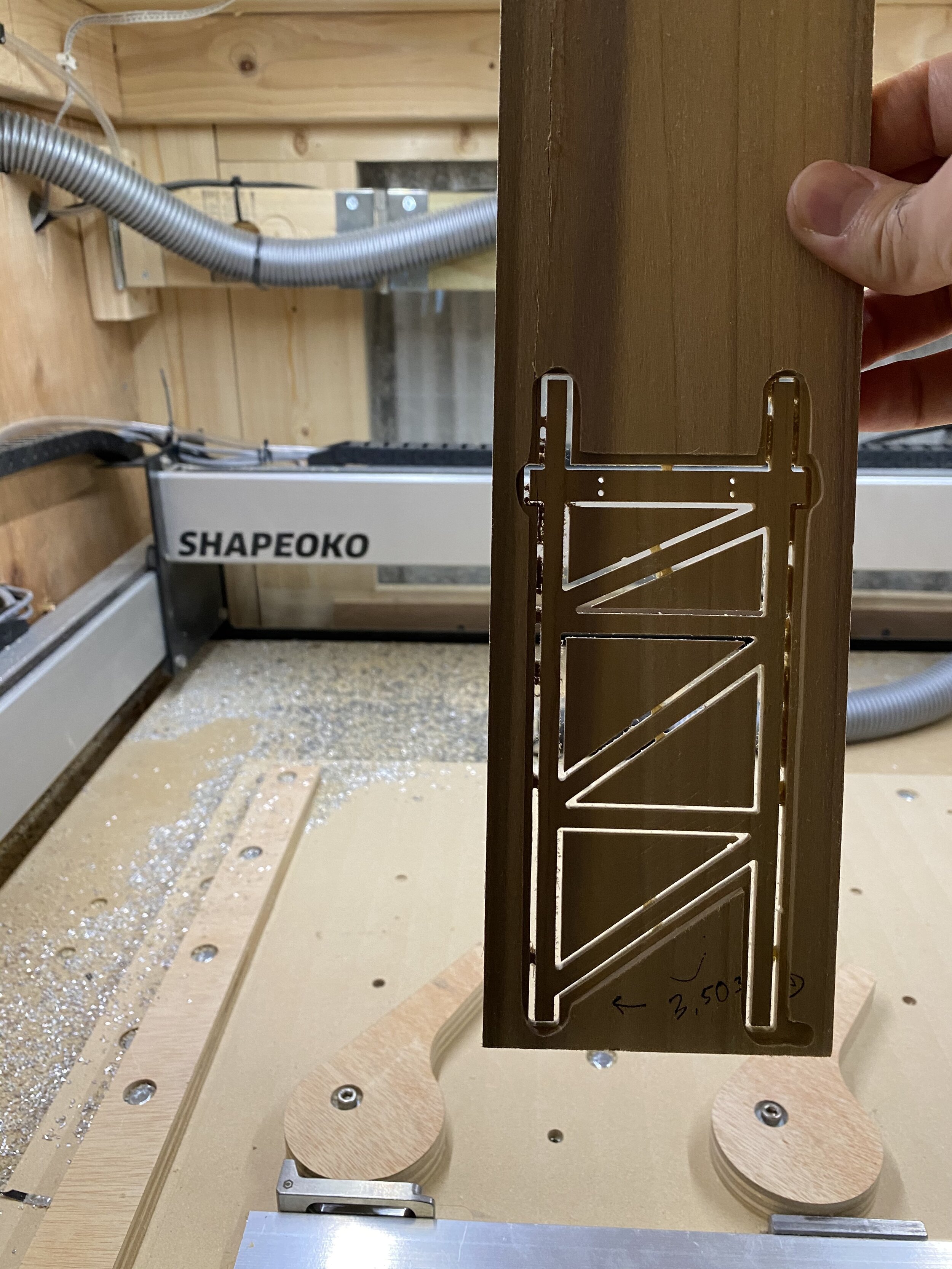
Shapeoko XXL Cutting its First Bent!

Shapeoko XXL Cutting its First Bent!

I decided on their larger size Shapeoko XXL due to its large cutting area. With a cutting area of approximately one (1) square meter, I could layout an entire baseboard foundation for the mini coasters and have the CNC mill the exact locations for the supports. Since I had little experience milling wood, I knew there would be a learning curve, too.

Fortunately, using the CNC Router along with Carbide3D’s intuitive software made learning the ins-and-outs of the Shapeoko truly enjoyable.

The Test Section

Through my practice cuts and design iterations, I knew fabricating a test of final assembly was crucial. The test section would have to incorporate each aspect of the structure and similar hardware that would be used on the final design. With this test section, it would be a good opportunity to develop miniature rollingstock (the cars).

Fusion 360 to model it all.

Fusion 360 to model it all.

The ride structure would be comprised of the supports, track brackets, and track rails. For a real roller coaster, the track is typically laminated and the first layer is nailed into the ledger (horizontal beam between supports) with 3-5 heavy nails. Now, the original nails come out or break off as the ride runs the first few times, but the weight of the track stack holds everything in place. Yes, the track is not connected to the ride. Most bridges are constructed in a similar way and the weight of the beams holds the bridge intact.

The materials I used for the test section and will make up the final version are Baltic Birch plywood for the structure (thanks to Matt from PrintMyRide…follow him on Instagram @PrintMyRide), Acetal Delrin for the track brackets and some type of flexible plastic for the rails. For the test section, the track rails were milled out of Delrin plastic, but I plan to use LDPE due to its flexible properties.

These screws are 1/16 of an inch in diameter and the bracket is less than a quarter of an inch in thickness.

These screws are 1/16 of an inch in diameter and the bracket is less than a quarter of an inch in thickness.

Once the track was connected to the brackets with “self-tapping” sheet metal screws, the overall ride became surprisingly rigid. Each track section was created based on the designed centerline, and the placement of the ledger is then based on the location of the track. The hardest portion of the test section proved to be the track brackets. I went through three (3) versions of the bracket prior to settling on the above version, and the final design looks and performs tremendously.

So let’s make more!

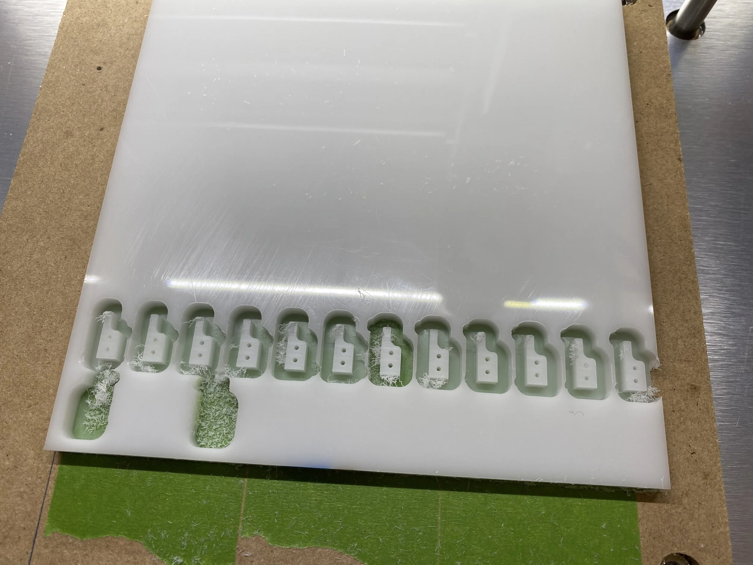
Had some white Delrin available, but final color will be black.  The drilled holes are 1/16” in diameter.

Had some white Delrin available, but final color will be black. The drilled holes are 1/16” in diameter.

Using the Shapeoko, I milled out the remaining parts necessary to construct the test section. Setting up in Fusion 360 (CAD program from Autodesk), and utilizing their new features for flat patterns allowed rapid production of the full design. Once the code was prepared from the design, I affixed the plywood to the CNC and began cutting the bents.

Successful Bent!

Successful Bent!

With all supports milled, brackets finished, and baseboard routed, I began to assemble the test section similar to an Erector Set. The small hardware was a tad difficult, but with proper tools from iFixit, such as miniature hex screw drivers, I was able to tighten the hardware appropriately.

IMG_0506.JPG

Being that this is only a test of the final assembly, a few things need to be solved: connection between track segments, sanding of supports, and handrails and walkboards. However, this little test was a success and allowed me to begin development of the cars.

More to come soon, along with videos to go through the progress!
It’s been a while.

As the title states, it has been a while. Much has happened over the past few years: moves, new jobs…etc. Although not much is an excuse for updates, it can be somewhat hectic resulting in lack of posting. Currently, the issue of illness around the world is a toxic icing on top of the cake of life. I hope everyone is well, first of all.

So why the lack of posting? I haven’t forgotten about the project and the plans for the future. Far from it. I’ve always wanted to continue posting and making videos of the progress, but when I had no time to progress then everything else suffered. So here is how things have been since 2016…

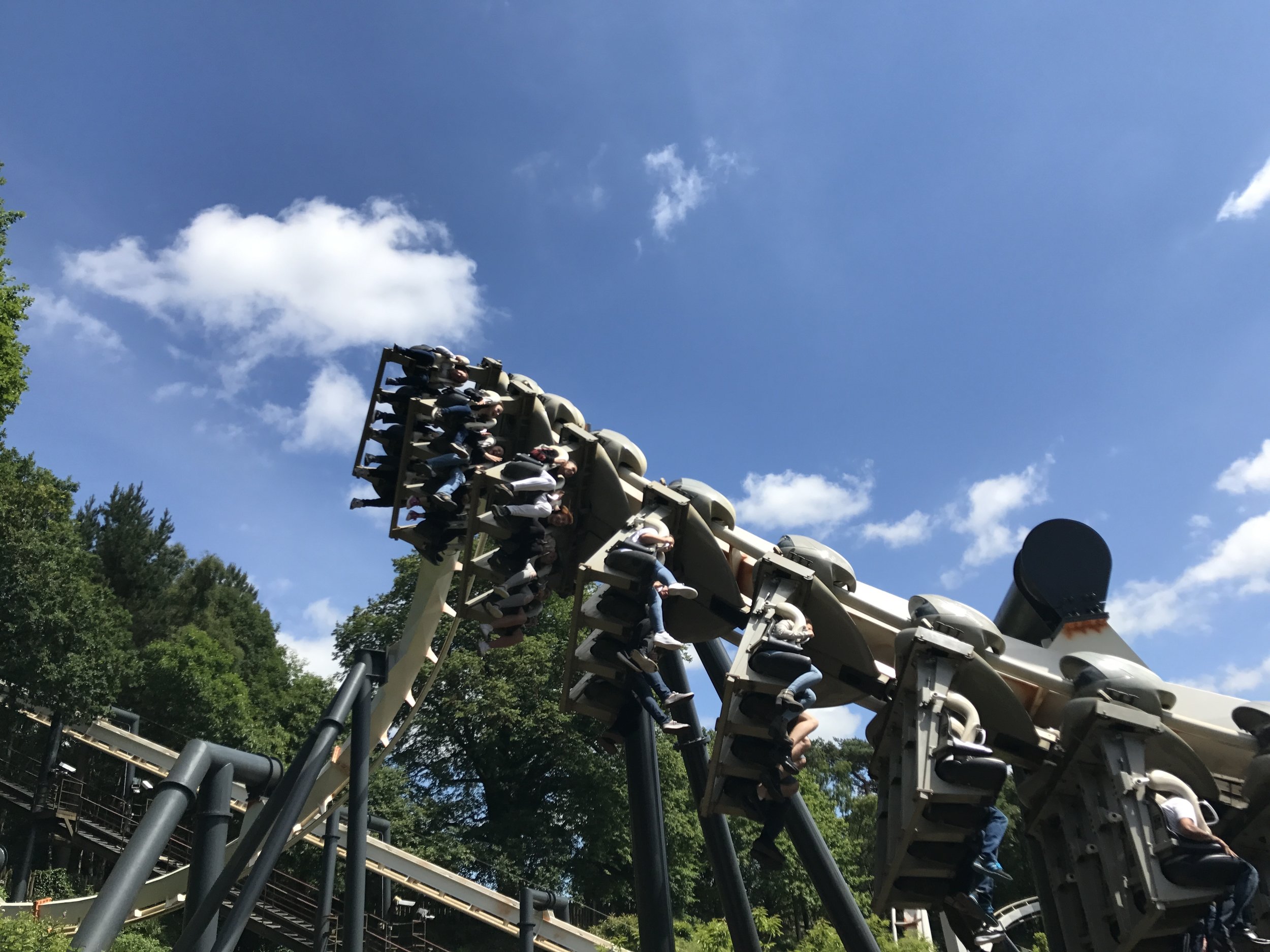
As some of you know, I worked for Great Coasters International designing wooden roller coasters. I worked on more than ten rides around the world. A few of the rides I personally oversaw construction onsite. The picture below was taken at Alton Towers during the Wickerman construction. This would be my last full coaster I worked on with GCII.

IMG_3522.jpeg

I spent nearly seven (7) months in Staffordshire working at Alton Towers and experienced many things I will never forget, as well as working alongside some truly remarkable people. Fortunately, I was able to explore the country and surrounding areas. But I am getting ahead of myself.

My progress began to slow as I was working in the United States on Mystic Timbers at Kings Island and eventually InvadR at Busch Gardens Williamsburg.

IMG_0987.JPG

InvadR Final Helix

Spending upwards of two (2) months in Virginia, away from my home in Cincinnati, Ohio was difficult, but it would be the precursor to my long journey that would take me across the Atlantic Ocean for almost a year. I would end up commissioning InvadR prior to heading to Belgium.

What is commissioning a roller coaster? Prior to opening an amusement ride to the general public many tests and quality checks must be completed per law, park codes, and manufacturer’s recommendations. Checking the controls, operation, structure, and accelerations can be a lengthy process at times, but those who build are first to ride. So, if any of you have seen the Busch Gardens video of InvadR in POV (point of view) format the park released prior to opening, I actually recorded that with my personal GoPro camera. I became the the third person to ride the coaster, too. Perks of the job.

Once Busch Gardens was complete, my job led me to opening a prolonged project in Europe: Heidi The Ride in Plopsaland De Panne, Belgium.

IMG_1309.JPG

This ride holds a special place in my heart since it was plagued with issues from the local government’s noise regulations. Long story short, I spend many months the previous year solving the noise issues and the coaster had its debut to the public in April of 2017. The layout is similar to White Lightning located in Orlando, Florida, USA, but Heidi’s structure is comprised entirely of wood. More forgiving than steel…

IMG_1279.JPG

Heidi The Ride was welcomed by the public, and is extremely re-rideable. While in Belgium, which was for one (1) month, I made friends with park staff and continue to chat with them to this day. I hope to return to Belgium, and the Netherlands in the future since words cannot describe the impact made on my life.

Once my monthlong stint in Belgium was complete, I was destined for Staffordshire, England for my next onsite project: Alton Towers.

Alton Towers had always been a park, almost Holy Grail in idea, that I could only experience in Travel Channel specials during my childhood. Never did I imagine that I would be able to visit the park, work at the park building a wooden roller coaster, and be given personal tours of the grounds. To this day, I regard Alton Towers as one of my favorite parks. The rides aren’t necessarily the most intense, but offer enjoyable experiences.

IMG_1715.JPG
IMG_1895.JPG

Beginning construction on Wickerman was a tremendous experience, and the bents in the picture to the left are for the initial drop out of the station during the approach to the lift hill. The company used to erect this coaster was based in Germany outside of Hanover, and the guys I worked with were some of the most skilled coaster builders in the world. They also brought some delicious German beer and food with them for us to share. Let’s be honest, there was plenty to go around.

For those of you who are unfamiliar with Wickerman, the main draw of the ride are the fly-throughs passing through a large burning (yes, actually on fire) structure. This structure is the Wickerman, and to build a wooden coaster through such an elaborate steel mess proved to be one of the greatest collaborations I experienced while working for Great Coasters. Timing and positioning had to be carried out so that no contractor onsite would be delayed. The code name for the Wickerman statue was “Big Bob” and we had many meetings to ensure we always referred to it as such.

IMG_2299.JPG

The topping of the highest point in the ride is a great achievement when it comes to building roller coasters. Since we had a mix of German, British, and Americans working to bring Wickerman to life, I thought it only necessary to represent those involved. Later we would have a few Polish workers, and those guys were some of the nicest, and craziest human beings I have ever met. Overall, I worked with a great group of guys to bring Wickerman to life.

IMG_2399.JPG

One contracting firm I worked with was a local architect that has been involved with many of the Alton Towers projects. The company Smytheman Architectural were the pinnacle of professionalism. I befriended a couple of guys from the company, and we remain in contact today. Since Smytheman is located in Stoke-on-Trent, I was fortunate enough to go to a Premier League match with a few of the guys in the company box. Those mighty Potters!

When you first start building a wooden coaster, once the structure is standing and plumb (vertical) you begin by nailing the walkboards and handrails. Once the walkboards and handrails are installed you can begin by adding the first ply or layer of track. In the picture to the right you see a few guys adding more walkboards up the lift of Wickerman, and the wonderful “kink” in the lift hill…that is a mind numbing story of why it exists.

IMG_2976.JPG

Swooping Drops and Tracking the Lift

As you can imagine, being in another country on another continent and on a job site building a full scale coaster makes it pretty difficult to build miniature ones. Nevertheless, I never forgot about proceeding with The Project, it was just difficult.

IMG_3366.JPG

While the structure and track are being completed on a wood coaster, the trains begin being installed and tuned for testing. Most of the cars are fully assembled prior to leaving the shop, but linking them together and proper shims to allow a tight fit are done in the field. Great Coasters has some of the best rolling-stock in the industry, and it was a pleasure to work on and with them. I even made a few modifications that are present today.

IMG_2782.JPG

Work continued on Wickerman even after I left England and returned home. While working, I had begun to think that maybe my time at Great Coasters was coming to an end. GCII’s business practices were changing and I wanted to pursue a graduate degree in engineering, so staying on the job site for the better part of a year started to seem less doable.

IMG_3295.JPG

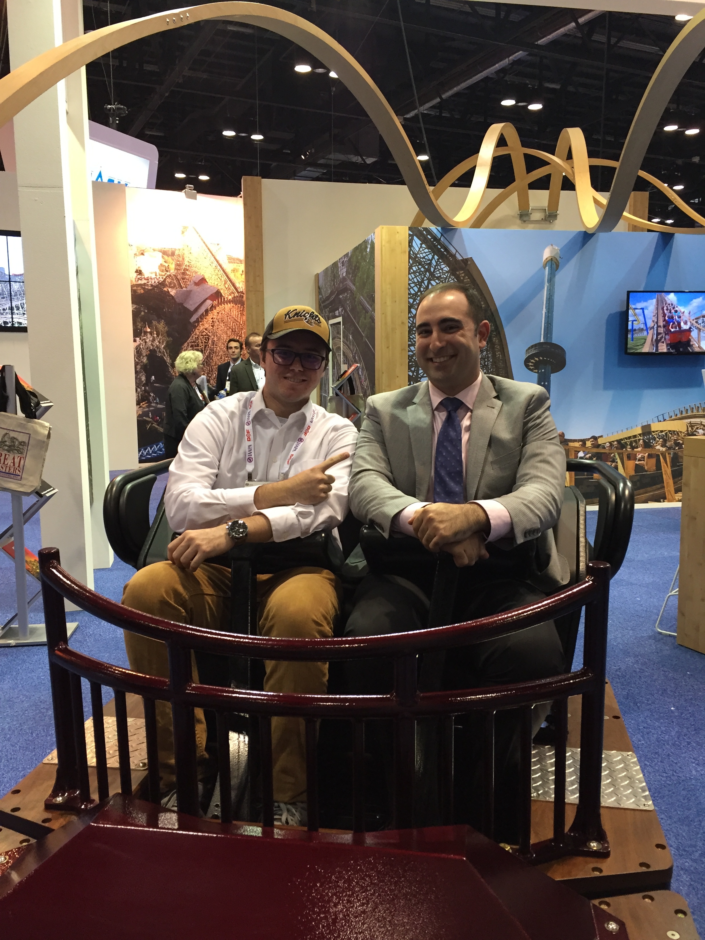
Upon returning home, I would attend my last IAAPA trade show in Orlando with GCII. It was bittersweet the leave the company I had admired from childhood and even sought to work with designing rides. But, it was something I had to do and I think things have a way of working out if you stay true to yourself, true to others, and your ambitions.

The strange thing is that I never know who is actually following along, so the chance to meet one of you guys face-to-face is always a tremendous experience, and I greatly appreciate your support. Don’t worry, I will continue with the mini rides.

IMG_3999.jpg

So what happened next? I began working in Atlanta after moving from Cincinnati. I worked for a small engineering firm until the next industry job presented itself. I now had a chance to resume The Roller Coaster Project fully. You can see in the picture that I make a bent building fixture to expedite the building process. In this time I also began to learn more about machining, having worked on real rides definitely helped.

It seemed like nothing was going to slow my progress on the coasters, and I finally was landlocked with no foreseeable travel to new lands on the horizon. But…things have a way of “working out.”

IMG_4749.jpg

Davey goes to Washington.

Through an industry acquaintance, I happened to accept a new position as a mechanical engineer with a newer ride company. This company had limited roles when it came to roller coasters, but it did offer a new area to expand my knowledge: motion simulators. Incorporating what I knew of coasters into the design of these complex motion simulating devices proved to be a great learning experience.

All the while, I had begun pursing a Masters in Mechanical Engineering, but this meant I would have to move yet again to a new area and put the project on halt. I know, can’t catch a break…kidding of course. But wait, did I have to travel overseas again?

The Land of China: Zhuhai

The Land of China: Zhuhai

Welcome to the land of China, population 1.2 billion+Dave. Having worked on three different coasters in China, but never having traveled to Chongqing, Chengdu, or Nanchang this was my first experience on the mainland. I had to oversea the completion and commissioning of a few rides in Zhuhai, located in the south near Macao and Hong Kong.

China was an incredible experience and I look forward to returning someday. The culture, food, and people were otherworldly, and I had an eyeopening time. This also allowed me to work with different cultures, including a large Australian population. But with great travel comes less than great progress on The Roller Coaster Project.

Midnight Ride: Lionsgate Entertainment World

Midnight Ride: Lionsgate Entertainment World

I remained in China for a little more than three (3) weeks. Perhaps the funniest part of the whole experience was meeting some colleagues from our Beijing office who happened to follow TRCP and discuss it with me. I mean, to travel more than 10,000 miles and find out the people you’ll be working with follow along? Small world, Project speaking. Their culture is remarkable and vastly different than any I had come across previously.

Chimelong Ocean Park - a great B&M wing coaster.

Chimelong Ocean Park - a great B&M wing coaster.

The streets of Macao

The streets of Macao

So that was the last of the traveling, right? NOPE! Next on the list was even farther…Malaysia.

Genting Highlands

Genting Highlands

For the next assignment I had to travel to Kuala Lumpur, Malaysia. More specifically, the Genting Highlands summoned my presence to their new outdoor theme park. But this time it was for a coaster!

IMG_5465.JPG

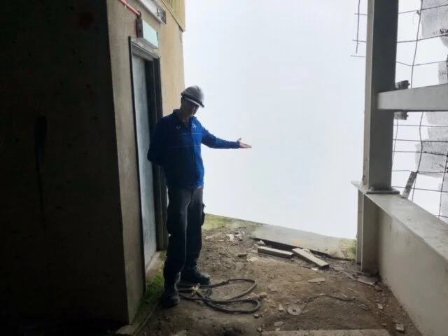
The fog at the top of the Genting Highlands was something else, and the frequency at which it would roll in was sporadic at best. This was my first experience working with a steel roller coaster, albeit a mine train and relatively small, it proved to be a worthwhile endeavor.

When the fog clears you realize it’s the opposite side of the mountain.  Good Luck!

When the fog clears you realize it’s the opposite side of the mountain. Good Luck!

An old colleague of mine and I thought it was ridiculous that there were so many open areas without barricades to prevent falling to some sort of death. Probably should be showing or mentioning this, but oh well. In all fairness, they did follow working guidelines and I do think that this just happened to be removed due to a delivery on the faux mountain.

Malaysia was an interesting place, and I would also like to return one day. My time on this project, or at least onsite was limited, but being that the plane flights to the site rounded out at about 23 hours you can see how little to nothing could be accomplished on mini coasters.

The Lifting Force is Strong with this plane

The Lifting Force is Strong with this plane

Bringing this long story to present day…

After much happening and much travel, I have now had some time to resume designing and small fabrication of the biggest little ride to ever be. I will be working on providing updates more regularly, and I hope to resume some YouTube videos too showing the progress. I appreciate any and all of you who have stuck with The Project these many years, and I hope my story provides some insight to the many delays and radio silences. In closing, I still think things have a way of working out as long as you never lose sight of what it is that awakens you on the inside. Not to be “profound” or anything, but remain persistent and follow what it is you care about.

Thanks guys!

More Ride Design, sort of.

First off, I apologize to anyone who’s not a math person, but also I don’t want to alienate those of you out there who are...so HA!  Designing a ride is math intensive, and more so nowadays that previously.  You’d be shocked at how many companies that engineer amusement rides today are bad at math, or hire a consultant to “check” their work.  Werner Stengel and his company is a prime example of a consultant hired to check math functions, smooth curves, and check accelerations.  

The basic fundamentals of roller coaster design, in particular, are simple Newtonian concepts from the outside.  However, as you delve deeper into the ride’s layout, you’ll notice a relationship between high order Calculus and Physics.  Many of the questions I get about ride design is “how do you get the centerline?”  Or, “is the ride designed in NoLimits?”   

NoLimits is a great simulation software, just Google it if you haven’t heard of it, and it has some great spline modeling.  However, it’s not used by the industry for anything more than just simulation purposes.  Most companies have their own math programs or spreadsheets designed to output necessary ride features.  There are a multitude of things not included in NoLimits since most people don’t realize they are factored into ride design.  Another discrepancy is that there are limits in real life (IRL for the kids).  These limitations have an ultimate effect on the ride’s final design: budget, space, rider data...etc.  

As for the centerline, previously I had mentioned a few different types of design processes.  If you think of a ride being similar to that of a building or a bridge, then you know you have to develop the loads and produce something to react them.  Just as you design a building, you have a set of codes for weights and accelerations to apply.  But unlike a building, you manipulate the loading in certain areas to produce a ride path.  The math can become a little chaotic, but when possible you should try to simplify it.

Remember, simplicity is key.  Most students and post college people want design to be super exact.  That’s not necessary, even NASA has a range of tolerances to stay within.  You should keep trying again and again to produce the results you want.  Change the methods slightly each time and simplify it as much as possible.  Focus on the concept, and use the math as a tool. 

IMG_0991.JPG

Ride Design, briefly.

Ride design is a symbiotic ​relationship between analytics and creativity.  While most math involves creative approaches to solutions, knowing how to balance the analytics for a thrilling and aesthetic experience is key.

IMG_2215.JPG

There are a few approaches when it comes to designing the ride centerline, most common are acceleration based and displacement based.  Although you can arrive at a similar solution, each has a benefit over the other.  ​

The benefit of developing a ride layout purely by acceleration is that your path is smooth and continuous to at least the third derivative, also know as jerk.  The drawback to acceleration design is placement of certain block sections and orientation of station and transfer due to the complex calculations to force desired outcomes.​

Now, with displacement design you can dictate every foot of the ride’s path.  This is great for layout purposes and can be altered later should the design need to be changed.  The drawback is, you must calculate the forces and angles to ensure continuity between elements in the vertical and lateral components.  ​

My thought process is to have a balance between the two.  Use them as tools in your workspace for the overall desired results.  But how are they solved?  Well, since all of these vary with either time or space, we use differentials.  For the young engineer or student, a good background in calculus and differentials will go a long way.  Many programs can help you perform the heavy math, too.  Matlab, Maple, and Wolfram are few examples of powerful computation tools.  They aren’t necessarily needed, but they do help make life easier.  ​

To sum it up, develop your model to produce desired results and calculate until you achieve them. ​

IMG_3743.JPG

Time Management

Since beginning graduate school a few weeks ago, I’ve had to find ways to balance working, school work, and ride building.  Needless to say, it’s not easy.  Whenever possible, I’ve been squeezing in design work and am actively setting up some time each week dedicated to ride building and video production.


IMG_4064.JPG

The first strike of home work.  The picture above is of advanced differential equations, which...sucks.  Not really, in my opinion, seeing as I chose it.  If you were wondering how rides were developed, well it comes from math like this!  So for any students or people wanting to enter the industry, definitely have a good grasp of math and physics.   

I’m still wanting to produce ride parts from the various wood working tools I have, and hopefully this week I can test it out.  If it works, which I think it will, I’ll have unlimited supplies to build rides.

Train machining and testing will follow once some structure goes vertical!  Updates soon. 

Enjoying Life

​This past weekend, I decided to have some “me” time.  Since starting graduate school recently, working full time, and build the most awesome mini roller coasters around, I needed a good little break.

A friend of mine, who lives in Orlando, FL, USA was having a party themed after “The Great Gatsby.”  It being one of my favorite novels, I was happy to head down from Atlanta and dress up as a somewhat dapper 1920s swell.  Still using the lingo today.  The girlfriend hates it.  Poppycock!​

IMG_4060.JPG

The Gatsby party was a nighttime affair, so that left the rest of the day to the girlfriend and me.  So what do you do if you have a day to do anything in Orlando? Disney!


IMAGE.JPG

​You may notice we are not going through the main entrance way.  That’s because we went to one of my favorites: Disney Hollywood Studios.  

IMAGE.JPG

Hollywood Studios’ newest attraction is “Toy Story Land.”

IMAGE.JPG

Our first stop in the park was Toy Story Land to ride “Slinky Dog Dash,” an adorably themed Mack family coaster.  Having known the guys from Mack Rides for a few years now, I really must commend them on a job well done.  Also, Disney did an excellent job of placing each patron in Andy’s backyard fully submerged in his toy box collection.


IMAGE.JPG

Having grown up with many of the toys Andy did, aside from Woody and Buzz who are movie creations, it was pure nostalgia.  The Disney Imagineers happened to nail every tiny detail of the toys, fine print, product characteristics, and even the aesthetics of the cardboard boxes for the crayons.


IMAGE.JPG

Perhaps the best part of any park, Disney or Universal, is that the staff remain in character throughout your experience.  In Toy a Story Land, this was no exception.  Staff would openly refer to patrons as “toys,” and people dressed as the famous green Army men would walk around and treat you like a character from the films.


IMAGE.JPG

It’s an excellent new addition to Disney’s already phenomenal lineup, and I can’t wait to return.   

The moral of the story, as you’d once hear at the end of cheesy 1970s cartoons, is that sometimes it’s good to step back and give yourself a break.  Enjoy the scenery, reconnect with friends, and simply find what makes you the happiest.  Of course, it doesn’t have to be Disney World or drinking Gin like some pre-depression 20s fool, but that’s what works for me.  


IMAGE.JPG

Happy Roller Coaster Day!

Apparently this celebration of roller coasters extends globally.  So... enjoy some photos and ride your favorite coaster this weekend! 


IMG_0049.JPG

Heidi The Ride at Plopsaland De Panne, Belgium. 


IMG_0588.JPG

The turn around, and a beautiful Belgian morning. 


IMG_0911.JPG

Mystic Timbers, at Kings Island in Mason, Ohio, USA. 


IMG_0880.JPG

Working on the “upper idler” for Mystic Timbers.   


IMG_1152.JPG

InvadR at Busch Gardens Williamsburg, in Williamsburg, Virginia, USA. 


IMG_1072.JPG

The dragon train and those beautiful Millennium Flyer wheels.  


IMG_2415.JPG

Wicker Man, Alton Towers in Staffordshire, England, UK.   This is the first, second, and third fly-throughs in the soon to be themed Wickerman.


IMG_3359.JPG

A fancy model of the ride. 


And to round it out, me with a fan at the IAAPA Trade show. 


IMG_3295.JPG

A Rookie Mistake

In order to mass produce the anchorage for the roller coasters, I needed as special machine setup. Basically, it s a specially made vise that allows me to place small angle aluminum in a repeatable position to drill the correct holes.


IMAGE.JPG

The base plate of the vise is close to the width of travel for my little CNC mill, which is 4 inches.  My current setup for making “one-off” parts is to use one of my jewelers vises.  Seems like no problem, right?  Wrong.


IMG_4031.JPG

Starting with a facing cut to clean the top, I used my typical 1/4” end mill.  Everything was working fine.  But the next operation was to adaptively clear metal.  This is where the isssue arrose.  


IMAGE.JPG

Notice how the z-column is tilted?  You should, it’s pretty apparent.  Well, I didn’t take into account the solid jaw of the vise overhanging on the back of the table.  So, as it worked it’s way around the metal it happened to run into the mill itself.  This sucks in so many ways when this happens.  I mean, it hasn’t happened in years.  But it makes you feel like a moron.  How could this much oversight take place? 

Afterwards, I had to tram the mill (square it up) and we are back in business.  The problem is, how do I make my custom vise? 

Well, I will be using my fixture plate that I purchased way back in the day at the beginning of my machining endeavors. 


IMAGE.JPG

But, the vise is still there?  Yes, I am going to make the jaws of my mini vise and use the fixture plate for spacing.  And...another problem.  Since the holes on this fixture plate are 10-32 (common 3/16” screw size), I only have 5mm screws...close but no cigar to sound like an old man.  I will be purchasing some 10-32 hardware and will continue to mill my vise.   

If you follow along on Instagram (@therollercoasterproject), then you saw my post about putting all machining videos in a playlist dubbed “Machining” on YouTube.  I want to have the videos for those who like machining, and the primary videos of ride building separated.  


IMAGE.JPG

Multiple videos are coming, so keep your eyes peeled.  I’m not sure why that’s an expression in America.  It’s weird.  But videos will be out as quickly as possible.  Also, I somehow fail to record my machining failures.  I always move the camera during the machine crashing... Oh well.   

-Coast on  

Ride Building Material

If you've been following along on our Instagram page “@therollercoasterproject” you may have seen some work with the table saw.  What I have been working on is creating a few cross-cut sleds for the table saw and band saw.  What is a cross-cut sled you ask?


IMG_4027.JPG

Now, this isn’t my image but it is a good example of a completed cross-cut sled.  The sled allows the user to cut repeatable and varying size parts.  How does this stack up for mini roller coasters?  I’m glad you ask.  

For our building materials, we have been using basswood for most of the structure and track.  This can be relatively expensive with a wooden coaster since there are so many components.  But, now that we have a thickness planer and a table saw, the doors are open to making our own building lumber!   

To sum it up, each 24” stick of 1/4” basswood is $0.55, and based on the desired amounts per stick we can get 3 8” sections.  Now, if we have a sheet of basswood at a quarter of an inch, we can cut up to 94 of the 8 inch sections.  The price per sheet is $15.80, and if we do the math we save a tremendous amount.  But what if we use pine boards for our structure?  An 8 ft pine board is roughly $8 at one inch thick.  Now that we have a thickness planer, we can get it down to our desired thickness and cross cut each 1/4” strip.  This saves so much money and allows for more control and inventory. 


IMAGE.JPG

These oak strips are cut to fit in the slots on my Ridgid table saw.  Once I place some 3/4” birch plywood on them and square it to the blade, you have an accurate cutting method.  


IMAGE.JPG

The oak board was actually twice as thick as shown in the picture above.  By using our thickness planer, it was brough to correct dimensions. 

The roller coaster will be made of pine!   

To Maker Faire or Not?

Now that I’m back in Atlanta, Georgia, I have the opportunity to return to the Atlanta MakerFaire. 


IMG_4026.PNG

Prior to moving to Cincinnati a few years ago, I had displayed roller coaster related gadgets two years in a row.  I basically “hired” a friend or my girlfriend for the weekend to help me out at the booth.  Being that I was still learning how to machine and fabricate ride designs, I didn’t have substantial ride structure to display.

This year, however, I am poised to display some working rides and full scale production.  I will also have some merch to sell/raffle off.  Of course, these are my hopes.  Just as before, I have packed my life full of events, trade shows, trips, and now graduate school.  But I will stay committed and focused. 

My goal: 

  • One fully operational test track with banked turns and magnetic brakes. 
  • A station section with platform. 
  • Two full length trains
  • one miniature ride test track
  • five metal classic TRCP cars for sale
  • shirts galore! 

Most of this is going to be documented via YouTube and this website.  So, if you’re interested and in the Atlanta area, then attend! October 27 & 28 at the Atlanta Freigth Depot.

Video Music

​I once worked for a radio station in a major market, and one thing I hold near and dear to my heart is music in video.  Having some music really takes a personal video, and transforms it into a real production.

IMG_4020.JPG

YouTube has a decent music/sound library, but I’ve been searching for a larger selection.  Perhaps more variety.  Having come a long way from my days of reusing “Maple Leaf Rag” in my videos, my last upload had a bit of a change.  Though I like the Dixieland Jazz and classic ballpark and amusement park music, having song selections that play on what’s being displayed is key.​

IMG_4019.PNG

Epidemic Sound​ is a subscription based repository of thousands of songs and sounds.  They allow you to place any and all song on to Youtube videos, and they won’t remove it should you ever cancel your account.  I am not being paid by them, I’ve just been researching. ​

It might be worthwhile for me since I want to focus 80% of the efforts into video content as I progress, and 20% social and blog.  ​

Has anyone out there had successes with Epidemic Sound or any other service?  Leave comments, since I’m curious and am looking to pick some good tracks for videos. ​

The Next Video


From the previous posts and videos, I have been uploading the building of ride assembly tools.  In the new video,  to come, there will be a bit of a saga.  What do I mean?  I will cover a test track from design to fabrication.  To keep with the whole “brevity thing,” for any of you Big Lebowski fans out there, I will do a portion on each video.  Going forward with the larger builds, I will do the same process.  Sadly, these things take much time and can become intricate.  Let’s see if it works!

Aside from bent building and ride layout design, there will be car and train assembly and mechanical components.  The test track will have a hill, banked turn, and ultimately a magnetic brake section.  For things like the magnetic brakes, I want to throw in a bonus video of calculating magnetic fields and dampening power.  I know, lots of stuff always on the horizon.  However, these next few videos will have ride building and finally testing. 

As for the cars, I have designed the car to mount a GoPro HERO 4.  In fact, the center of rotation, called the heart line by some Swiss manufacturers (B&M), is actually at the center of the lens.    

Either way, more things to come soon!   Be sure to check out the YouTube channel and subscribe to see all the rides in motion!

IMG_0007.JPG

Correcting The Mistakes

As with all fabrication and manufacturing, if you make a mistake cutting something it can’t usually be undone.  When it comes to subtractive manufacturing, like CNC machining, then you really can replace the metal once it’s milled away.


IMAGE.JPG

On the eve of building some ride sections, I had the idea to modify the snazzy building tools I made last week.  Since the outside post dimension is what I choose to govern the ride width, I milled out the slot a bit wider than the original 0.25 inches.


IMAGE.JPG

Since these parts were already milled, I had to accurately locate the part in all coordinates.  This was a good time to use my z-axis touch off setter.  It worked well.   The only drawback is that it’s 50mm in height, and I am limited with my z-axis travel on my little mill.

Now the error on my part... 

I didn’t mill deep enough when widening the pockets on the parts.  So, I tried to manually control the mill.  Sadly, I happened to run the end mill into the finished edge.  This now makes my out-to-out distance 4.78” instead of the design 4.75”.  I know, it’s only a 32nd of an inch, but the upper section is dead on at the latter of the two numbers.  It should be okay for some test bent sections and a model track, but for the final rides it has to be redone. 

In summary, don’t mess up.  It sucks tremendous ass, and it takes more time.  Focus on not rushing and always triple check measurements.  Especially if they are created in a computer program to be run by another computer.  Garbage in equals garbage out.  However, I will have a video out soon showing some ride building.  Later there will be a video of making the foundation anchors, too. 


IMAGE.JPG

A custom work vise for my foundation anchors!

Building Tools and Ride Structure

This week has been focused on the setup of the bent building tools.  

In the linked video, I machine the full sized bent building tool.  The post spacing is 4.5 inches, which is 1/24th the size of a modern wooden coaster post spacing.   

The last thing I will have to machine to make the ride structure repeatedly is a drill guide.  The drilling guide will provide correct locations for my small hardware: 1/16” nuts and bolts.  There will be a lot of hardware on this coaster, much like the real rides.  I mean, this is a real ride, just ridiculously small. 

After working on this for so long, sorry guys, I noticed the importance of creating the tools I will need to build my creations.  However, once the tools are made I can make as many of these rides as possible.  I shall cover the globe!  Yes, globe, meaning spheroid or ellipsoid.  None of that “flat Earth” bull shit on this page.  I mean, really?  People are still questioning this fact?

well...

Aside from that, checkout the video.  Thank you guys and gals for your support! 

IMAGE.JPG

Bent Building Tools

This week I have been focused on creating the necessary bent building tools to ensure accurate and repeatable parts.  From the video last week, I machined a miniature version of the "bent builder" tool I will be using for the mini coasters.  However, this week is focused on the larger scale ride which is 1/24th the size of the real thing.  In other words, it's massive.  

The post spacing is 4.5 inches.

IMAGE.JPG
IMG_3995.JPG
IMAGE.JPG

You'll notice that the size of the stock being machined in the pictures above is much larger than what was featured in last week's video.  One thing to make sure of when working with large parts and a smaller vise is keeping the part against the parallels and that you have adequate clamping pressure.

The parallels are machine ground to be flat within 0.0001", at least these particular ones.  

This week's video will be focused on the fully bent building tool, and there will be a threaded rod with two support rods added.  Ideally, this will help create structure rapidly and accurately.

IMAGE.JPG

When you get tired of watching the mill doing it's thing...

IMAGE.JPG

You can see, somewhat, the chip pan filling up with more and more aluminum.  Once there is a significant amount, I will recycle it.  The key is not to cross contaminate one metal with another.  

In all, the mill is running well and I have had no fails this week...but there's still time.

Another fixture to build this week, which will be in next week's video is my anchor vise.  This self-made vise will allow me to make my anchor angle aluminum parts rapidly.  Since there will be so many posts, I will need to make a great deal of them.  I will also have to make a cutting jib to use on my band saw.  But, one thing at a time.

FullSizeRender.jpg

In the picture above, you can see the difference an old (left) versus new (right) end mill produces.  The larger part is, and I mean this, the best thing I've machined so far.  Back in my 3D printing days, I refined my process fairly well.  Now, it seems that I am finally getting the hang of machining.  The one thing I didn't account for on the new end mill is that there is a slight corner radius; however, the part is smooth and shiny as can be.

Questions As of Today: Part 1

As things come back into full swing, I’ve had a few questions asked.  I will post a blog response as more of a summary to what has been asked on the various platforms.   

One of the most commonly asked questions pertains to how I created the data to build the ride or to build these rides.  To sum it up, I derive measurements and angles to place wooden members in the correct places based on the ride’s designed layout.  I know, vague.  Well, think of it like designing a building: you start from the top and work your way down.  As the building gets heavier the farther down you go, more structure is required to support the increasing loads.  With that being said, from a developed ride centerline you can provide a nice cushion of structure to support the varying loads.   

As for the actual physics and math to analyze these forces, I have a few videos on basic ride calculations on YouTube.

Now, for the angles and measurements...well they come from me or can come from you!  The crazy thing about science and engineering is that you need to make initial assumptions and test them to see a result.  As it pertains to a roller coaster, you are looking for a desired feel or experience.  To achieve the aforementioned ride experience you create numbers to match (or best you think).  Then you analyze what happens along the ride.  If these numbers represent what you’re shooting for, then you create the supporting aspects of the ride.   

To put it basically: set your parameters and make it fit within.  You’ll get all your angles and measurements, trust me.   


IMAGE.JPG
IMG_2932.JPG

Testing helps evaluate measured data versus theoretical data.  Heidi approves.

The week ahead

After a weekend of thought and making machining code, we have the week ahead of us.  As stated in the recently uploaded video, this week’s YouTube extravaganza will focus on building ride structure.   

To build ride structure, you have to focus on more than just the above structure.  We have to have a way to secure it to our “ground” which will be plywood.  Previously, I had CNC milled wood with a circular hole, filled it with glue, then pressed the rectangular posts in the pocket.  This wasn’t bad, but I would prefer a more repeatable and authentic style of anchorage system. 


IMG_2530.JPG

Prior to working in the amusement industry, I had ideas of placing angle metal (aluminum most likely) to connect the structure to the foundation.  The picture above is during the construction of Wickerman at Alton Towers.  Having worked with these anchors now, I will be implementing them into my ride construction.  This is for the full sized mini ride, by the way.  Yes, it was a weird sentence.

To make these anchor brackets hundreds of times, I will be making a drilling and cutting jig to repeat the process.  Ideally, it should connect the posts correctly and once the structure is standing it will be aligned vertically and horizontally or called “racked.” 

I’ll have more updates throughout the week!

Making YouTube Content

As some of you probably know, I use YouTube display my builds/machining, but I’ve been sporadic in the past.  Last night I wrapped up editing and narrating my latest video: check it out on YouTube.

IMG_3975.JPG


In order to build these mini coasters, I decided to machine a precision jig which allows accurate structure spacing.  My later videos will be heavy in ride building, and I think they are more of what people want. 

I plan on uploading videos each Friday and want to set out to complete one portion of a larger project in each video.  Upon looking over my previous videos, I’ve noticed that they need more story telling/direction.  Last night I did some voiceover work, and with the setup I have it turned out pretty good.  I was a tad bummed that my mixing board won’t exactly work with my computer since updating the operating system, but I can record separately and piece the files together. 

This week was a bit of a struggle machining since I haven’t done it in a while, but I’m confident that later videos will have more content and focus a little less on the milling/turning of parts.  The cars will be machined in a few weeks, now the structure takes priority.  Hope you enjoy! 


The First Part

Last night was one frought with successes and failures.  The first part in this long process of creating miniature roller coasters was successfully milled.  That is, after a few days of failures.  However, growth comes from setbacks.   Or a large pain in one’s ass.


IMAGE.JPG

You’ll notice from the picture that much has changed from the last few posts.  Most notably, the use of a vise instead of superglue and a sacrificial plate.  Nothing against the superglue, but I know this method repeatedly works. 

Now the issues... 

I used whatever stock I had in supply, and it’s dimension was roughly 3/4 inches.  That works all well and good until you square the stock for milling and your closest parallel is just large enough to cause the end mill to hit the vise.  (David hangs head in shame).  


IMAGE.JPG

Somehow, I managed to not get the happenings on film or take a picture of it.  I have much of the aftermath that will be present in Friday’s YouTube video.  This failure caused the end mill to chip, thus, it’s basically worthless.  S***.  


IMAGE.JPG

I destroyed one of my aluminum cutting end mills, but fortunately I had a three flute steel cutter on hand for the win.  In the picture above you can seee where it collided with the vise and part.   

Before pushing forward with machining, I altered the design and g-code in Fusion 360.  After updating everything, it was a complete success.  I even ramped up the spindle speed. 


IMAGE.JPG

This part had many firsts, of which milling dual sided pockets with my 1/8th inch aluminum cutter with lots of coolant.  Basically the area to place the wooden supports to keep them straight.  The other first was chamfering the part once completed.  It worked successfully with my quarter inch spot drill cutter.

The part can now be used to build ride bents, and the next video will show it in action!  As said before, the video (with bloopers) will be up tomorrow at 10 AM EST and subsequent videos will be up on Fridays. 


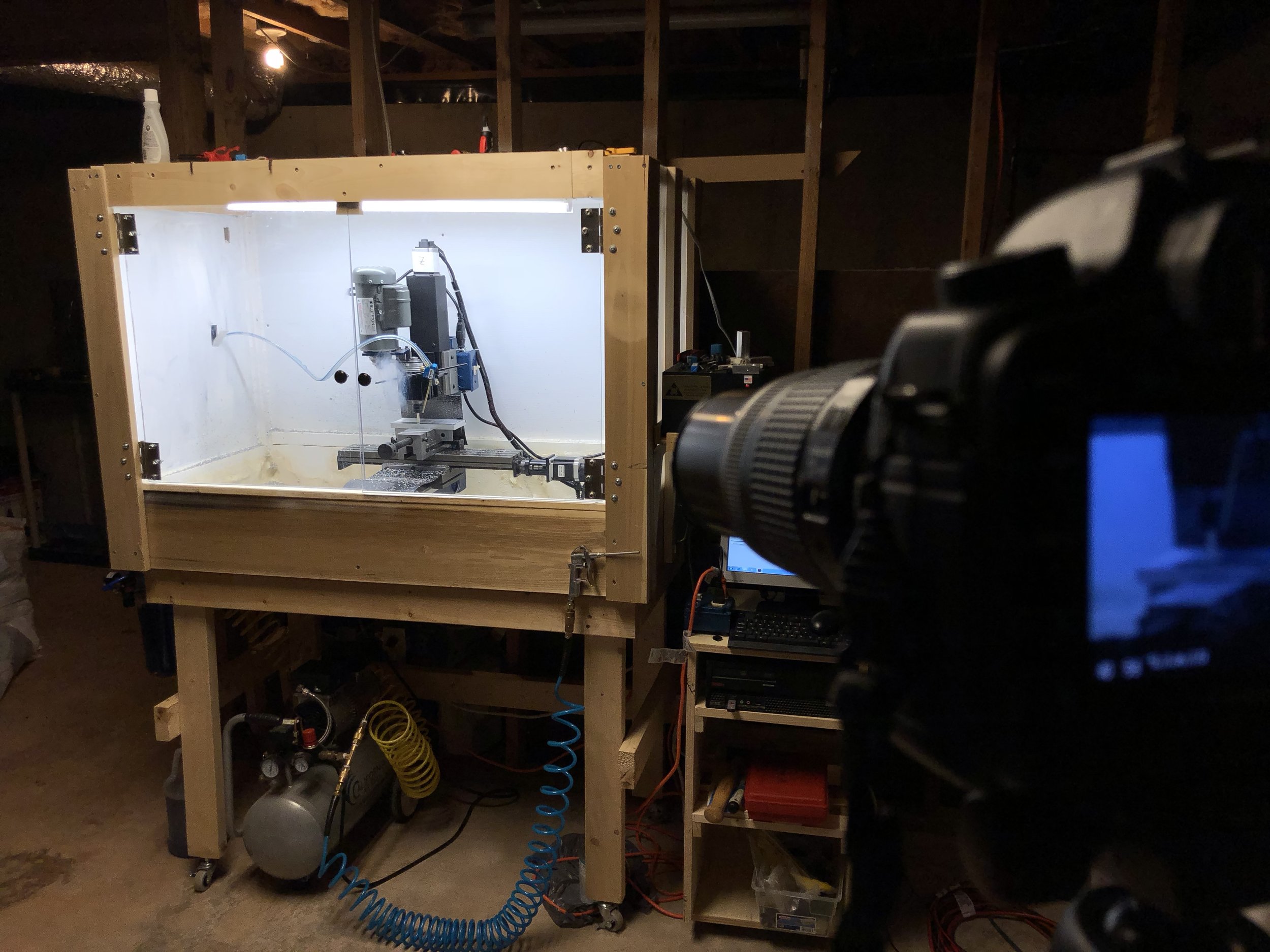
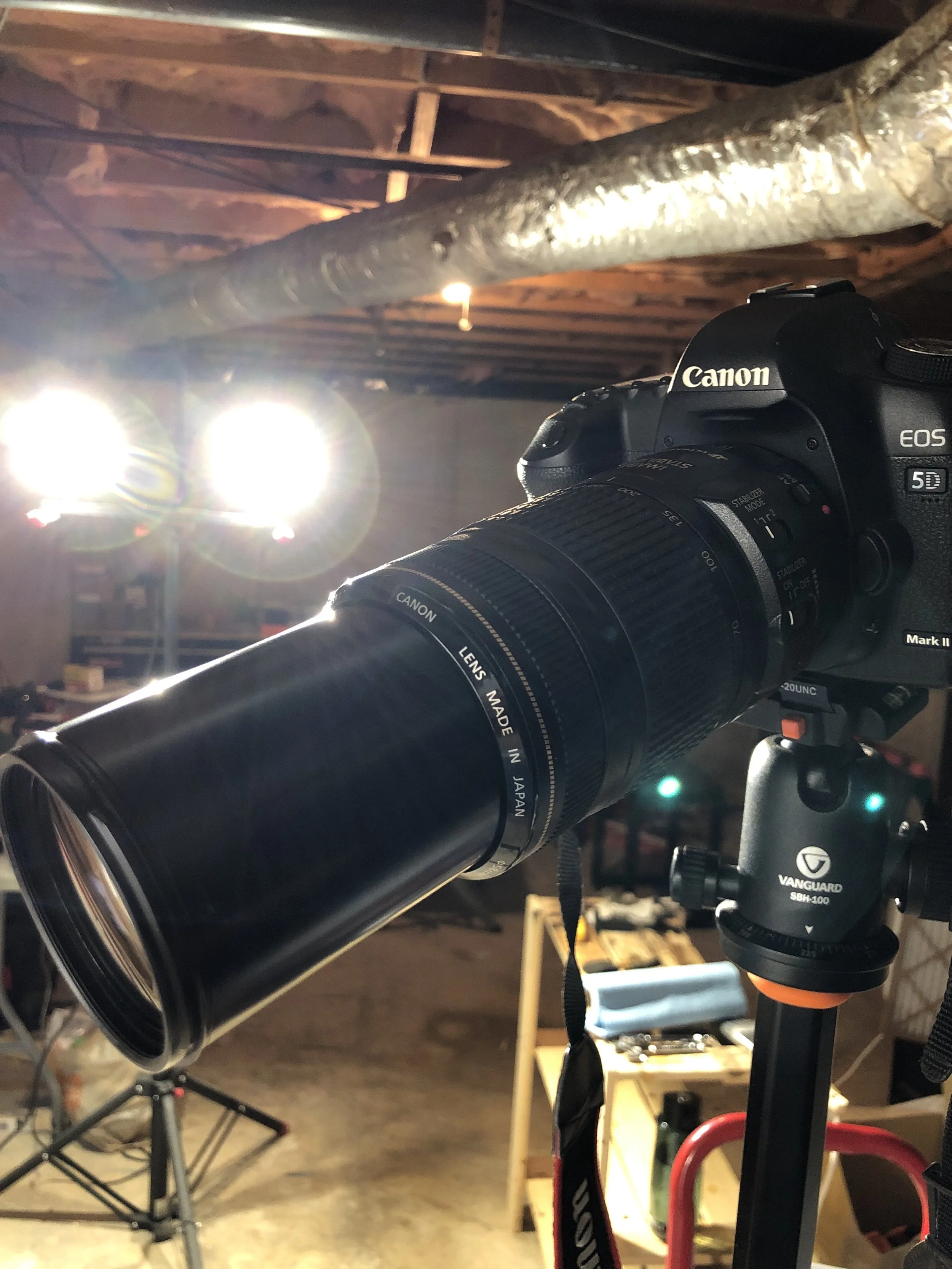
A little excessive?  This lens makes some beautiful photos and videos.  But, don’t forget to pour one out for the fallen end mill.  

A little excessive?  This lens makes some beautiful photos and videos.  But, don’t forget to pour one out for the fallen end mill. 


IMAGE.JPG

Milling Fails

My shenanigans wouldn’t be complete without milling failures.  As I began filming and running the code for the first part, the superglue happened to fail and the part come loose.


IMAGE.JPG

Quickly, I stopped the mill and assessed the situation.  Since my last milling attempt, I placed a center screw to hold the aluminum plate and milled out a relief pocket to remove finished parts.


IMAGE.JPG

I figured it was a mishap and decided to try again.  I placed new Frogtape and superglue, applied pressure, and hit “cycle start.”


IMAGE.JPG

 ...and another failure.

About this time, I was becoming frustrated and had collected a lot of footage of these subsequent mishaps.  I am going to throw them into this week’s video.   

My thoughts now are: cleanliness of mating surfaces, and pressure applied for glue to dry.  However, I’m not sure if either of these will change what’s happened two times so far.  Going forward, I will just mount my vise and clamp the parts normally.  This will also be in the video.   


IMAGE.JPG