
What the Track?
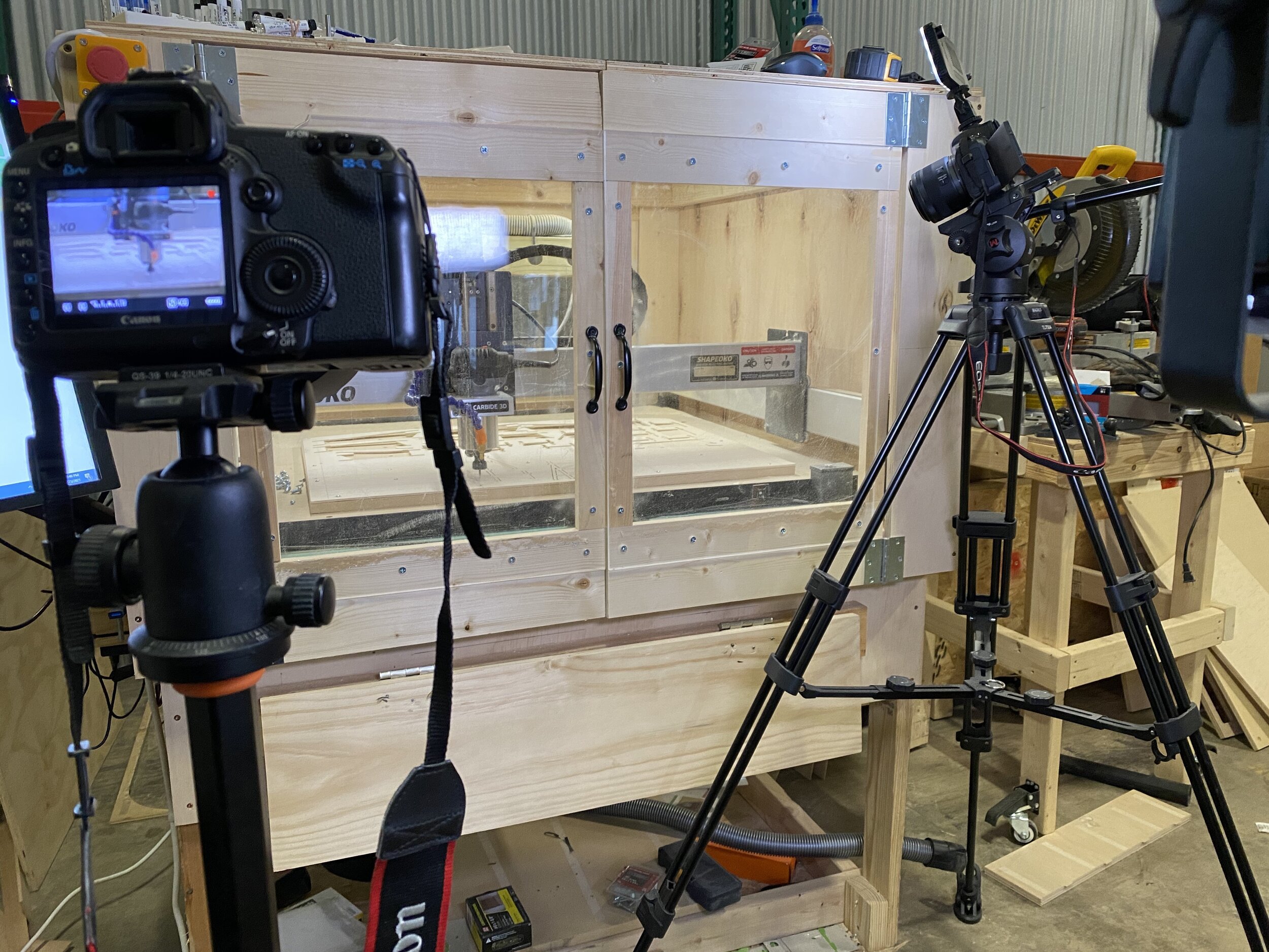
/A problem with building something functional, yet small, is the method of fabrication. From the beginning of this project, I have had issues with 3D printing. Due to my current circumstances, I have returned to the fabrication process of melting plastics layer by layer. Though I think CNC fabrication is superior for most things, unless you purchase commercial grade 3D printers, I have no room to incorporate these technologies. Lack of space!
3D printing technology at the consumer level has grown to mimic commercial capabilities in recent years, and I can actually fabricate intricate designs accordingly. However, there is one area that must be as close to design as possible: the track. There are always margins built into every design, but as things get smaller and smaller there are finer margins to operate within.
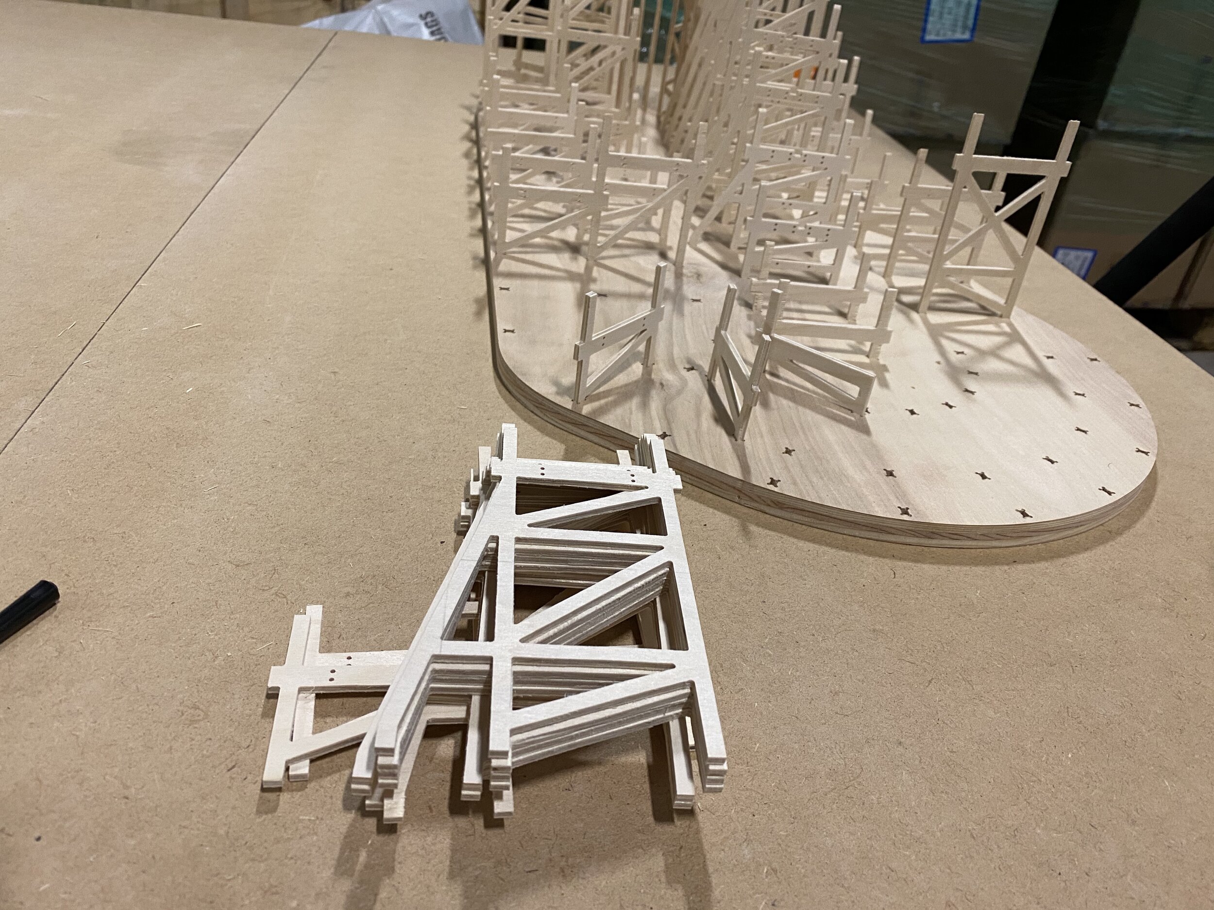
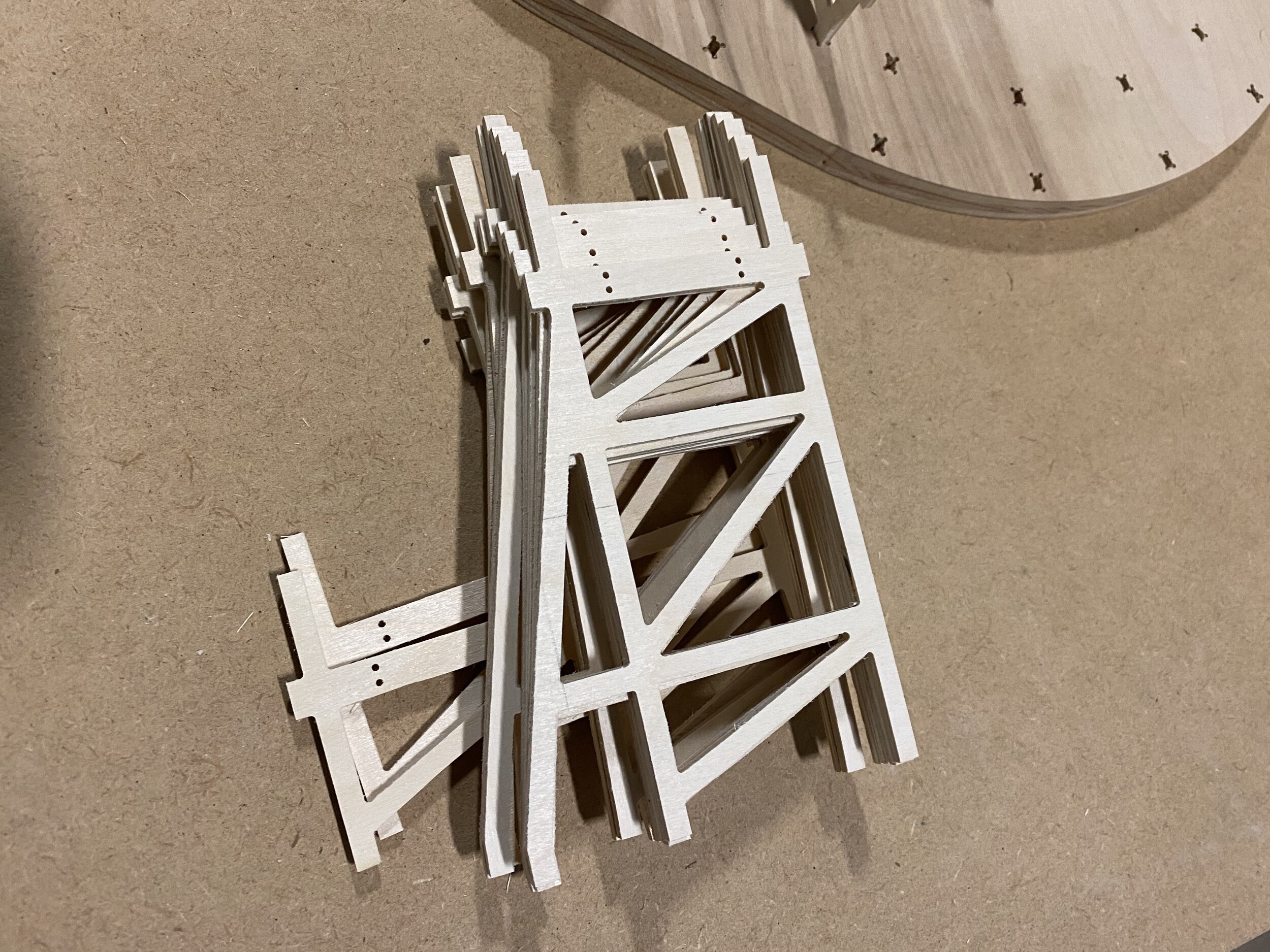
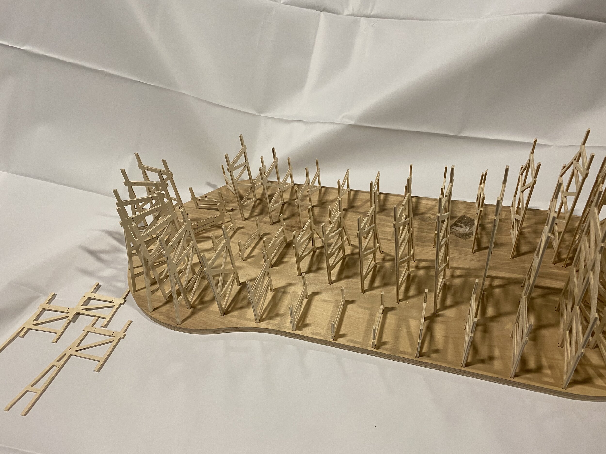
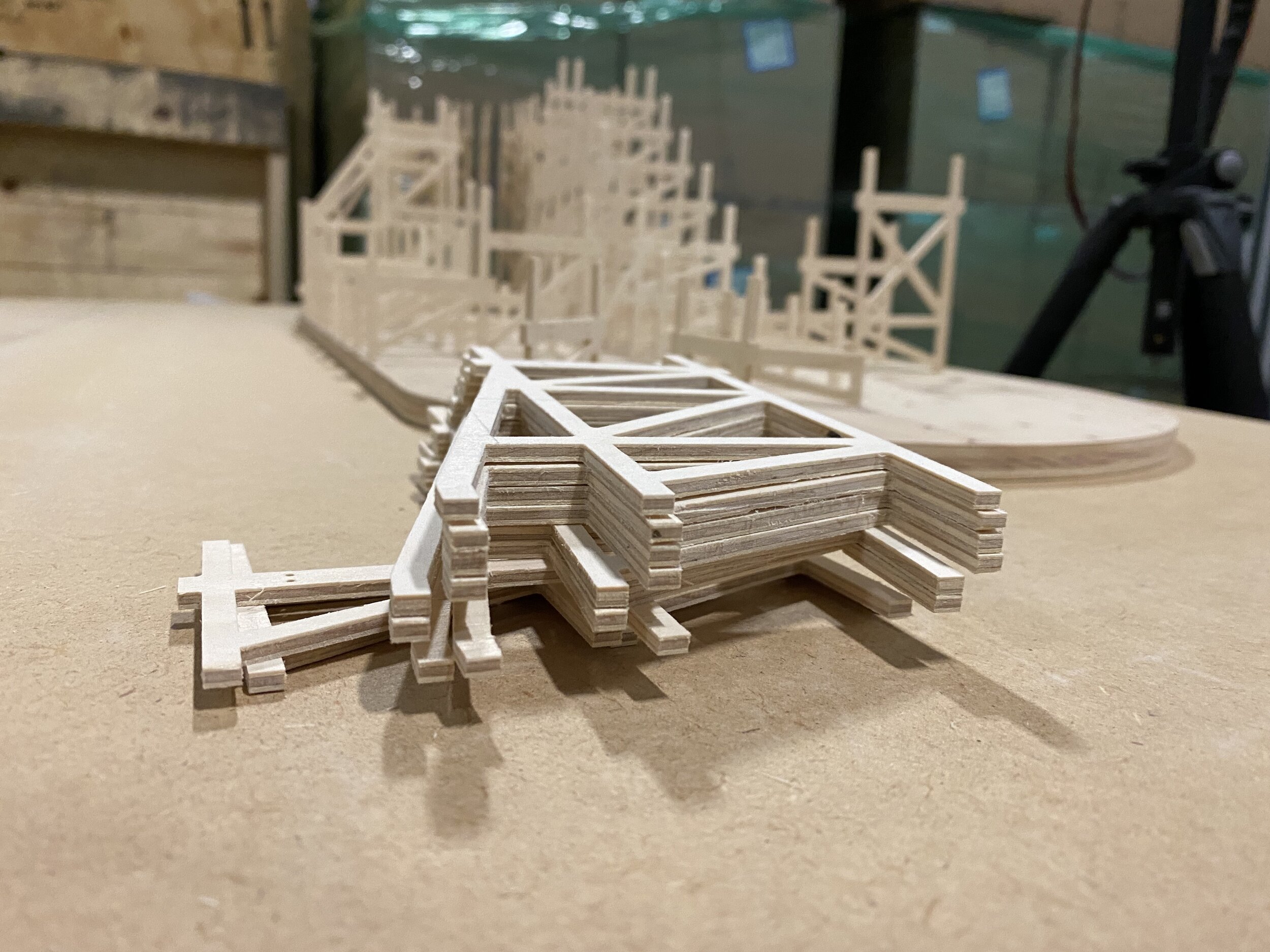
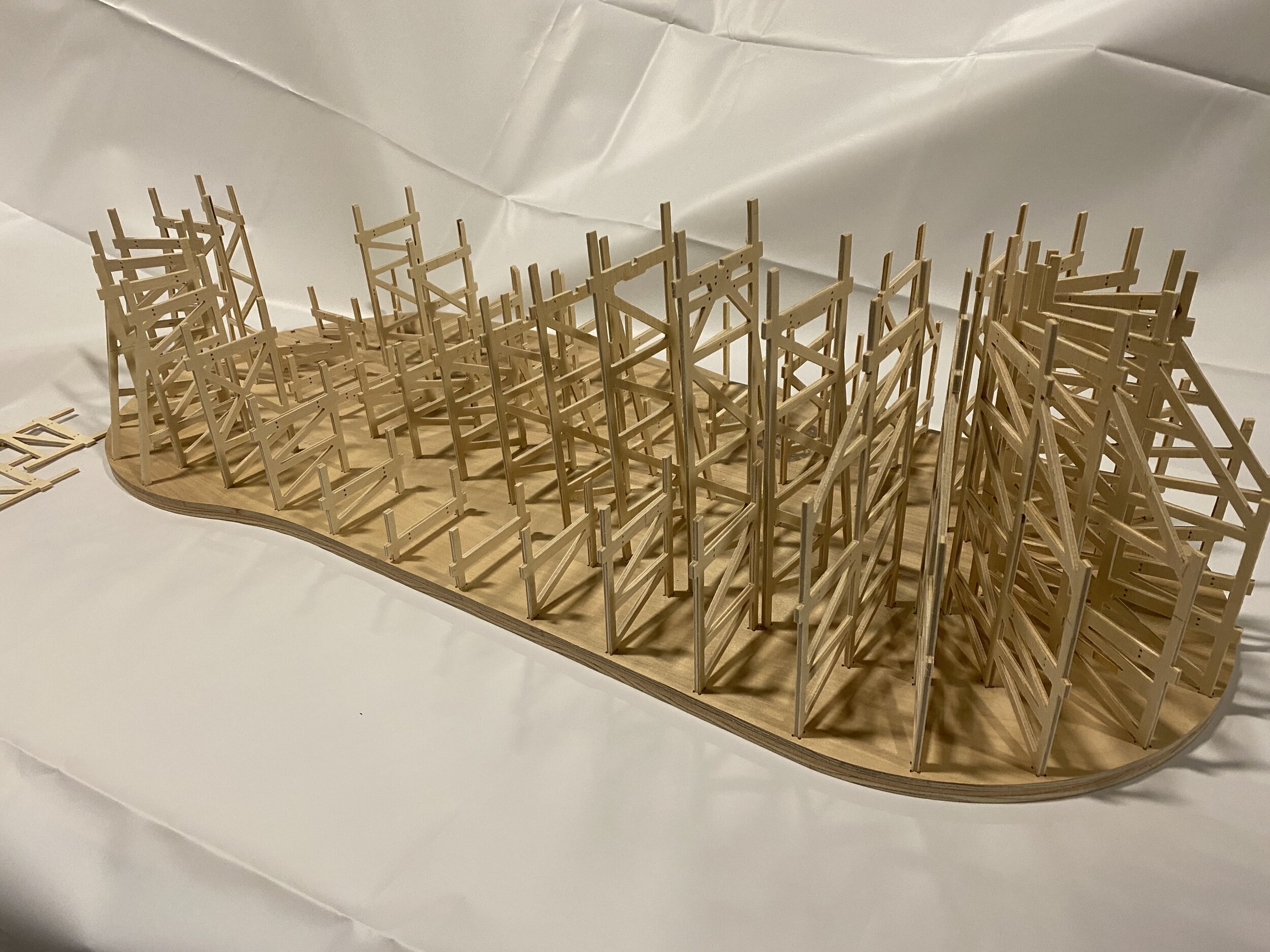
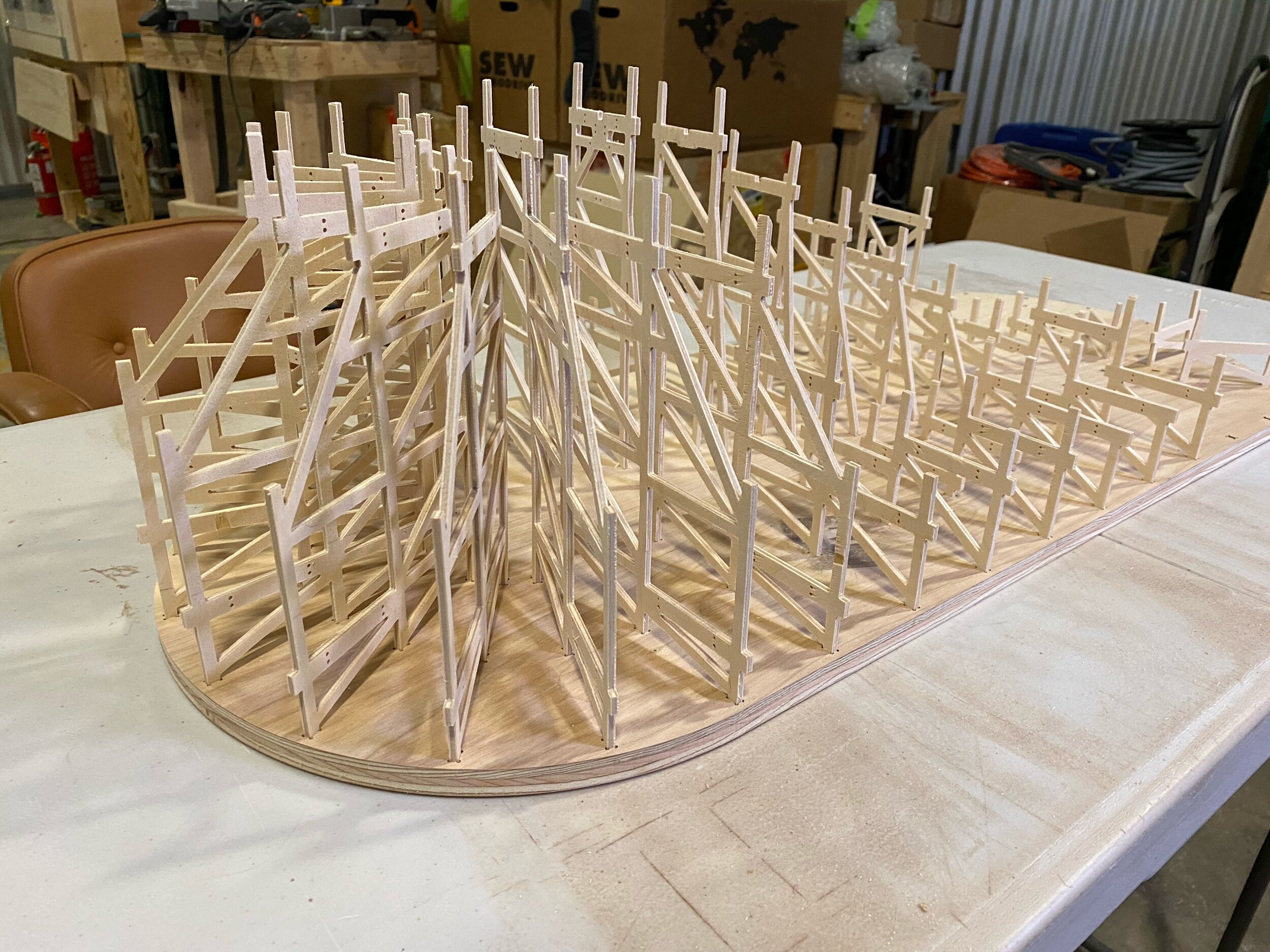
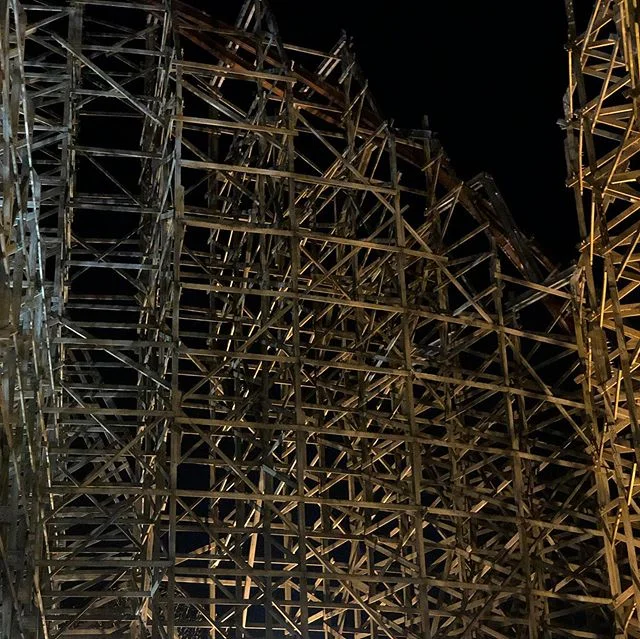
The few ideas I have been playing around with in regards to track fabrication and execution fall in either a modular design or a more traditional design. What does that mean? Well, in the modular design process, each track area is made into defined sections and combined with either a mating flange or longitudinal gusset plate. Both practices are standard in structural design and have been implemented in real ride design. The more “traditional” method is assembling a wood coaster via laminates of wooden boards from support to support. Now the issues…
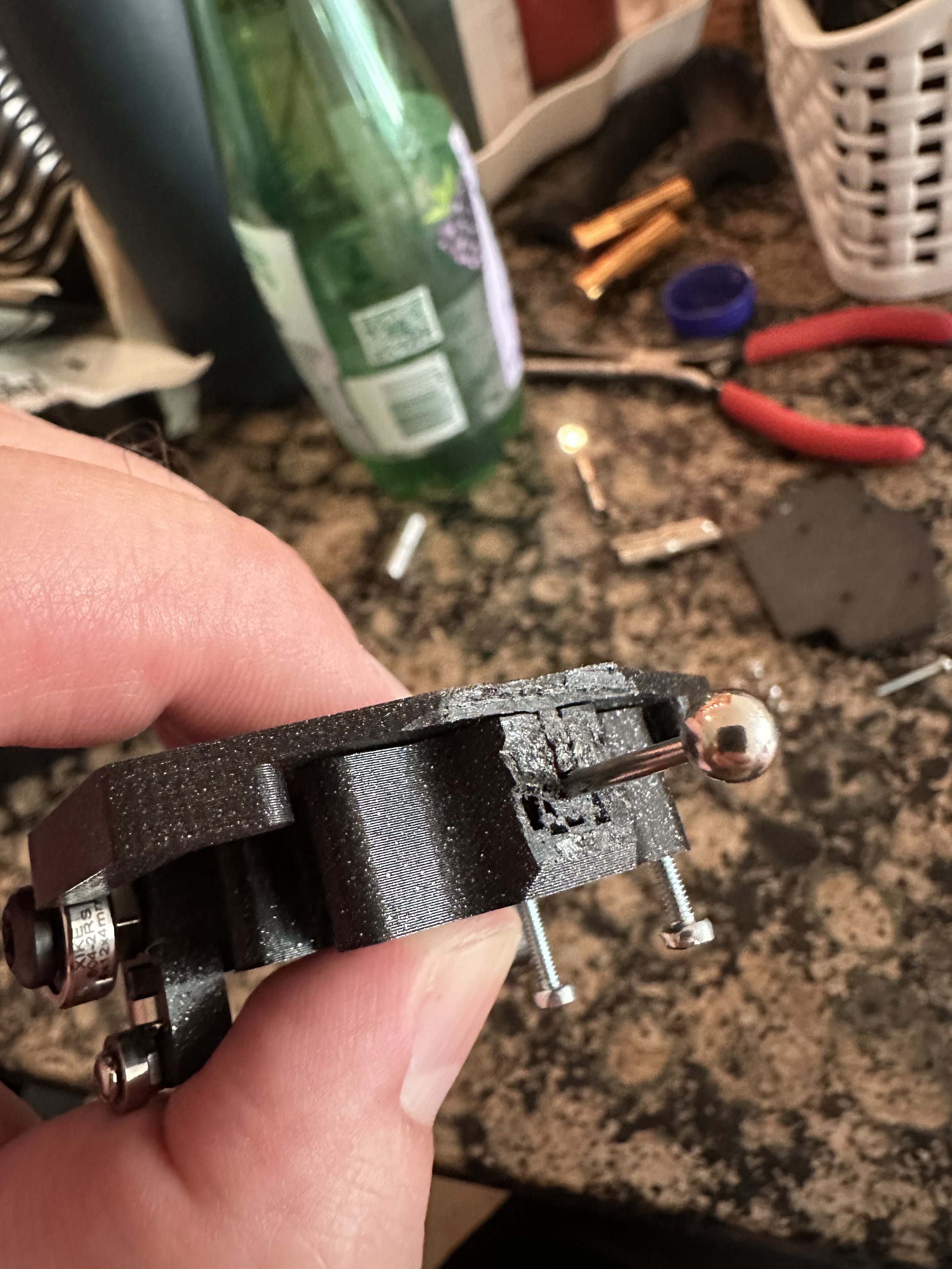
With everything being so small in nature, making each track piece into bolted sections seemed promising. I was quickly brought back to reality and noticed the limitations of FDM 3D printing: melted layers. Even using a finer nozzle tip (0.25mm), there were many inconsistencies in the final models and components based on the melting plastics. There are 3D printers that use UV curing of resins to produce extremely precise models; however, far too many fumes and particulates are produced to keep in a confined space.
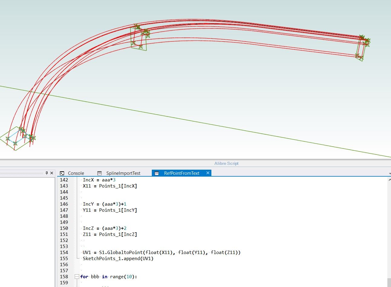
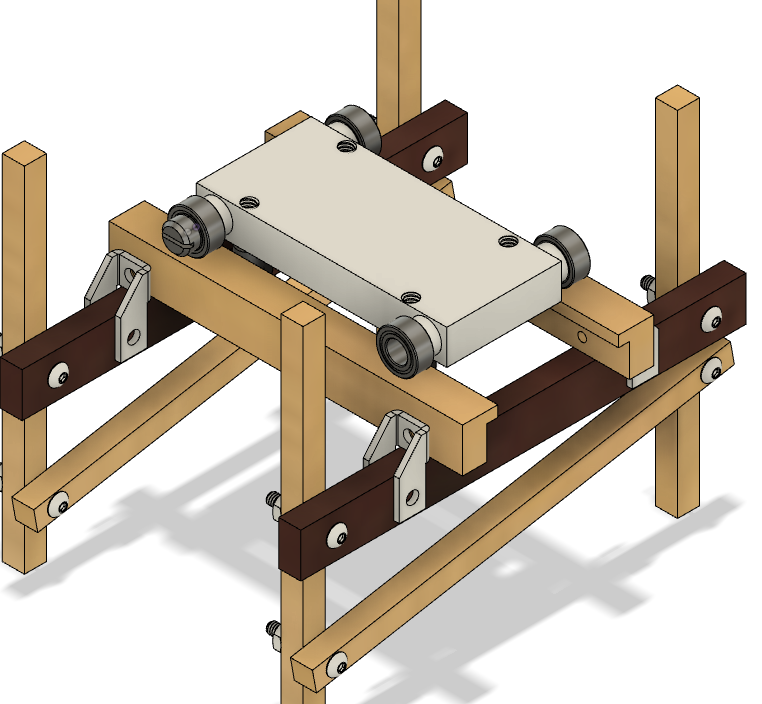
The real issues began to present themselves when I was generating flange connections or gusset plates. Inconsistencies in the print left little to no margin to align track sections or ensure a smooth riding surface. When I say riding surface, this does not mean the top riding rail, but rather the guide rail areas. For the top rail, I created a program to flatten 3d curves to make the pieces better suited for fabrication. This rolls into the next building method…
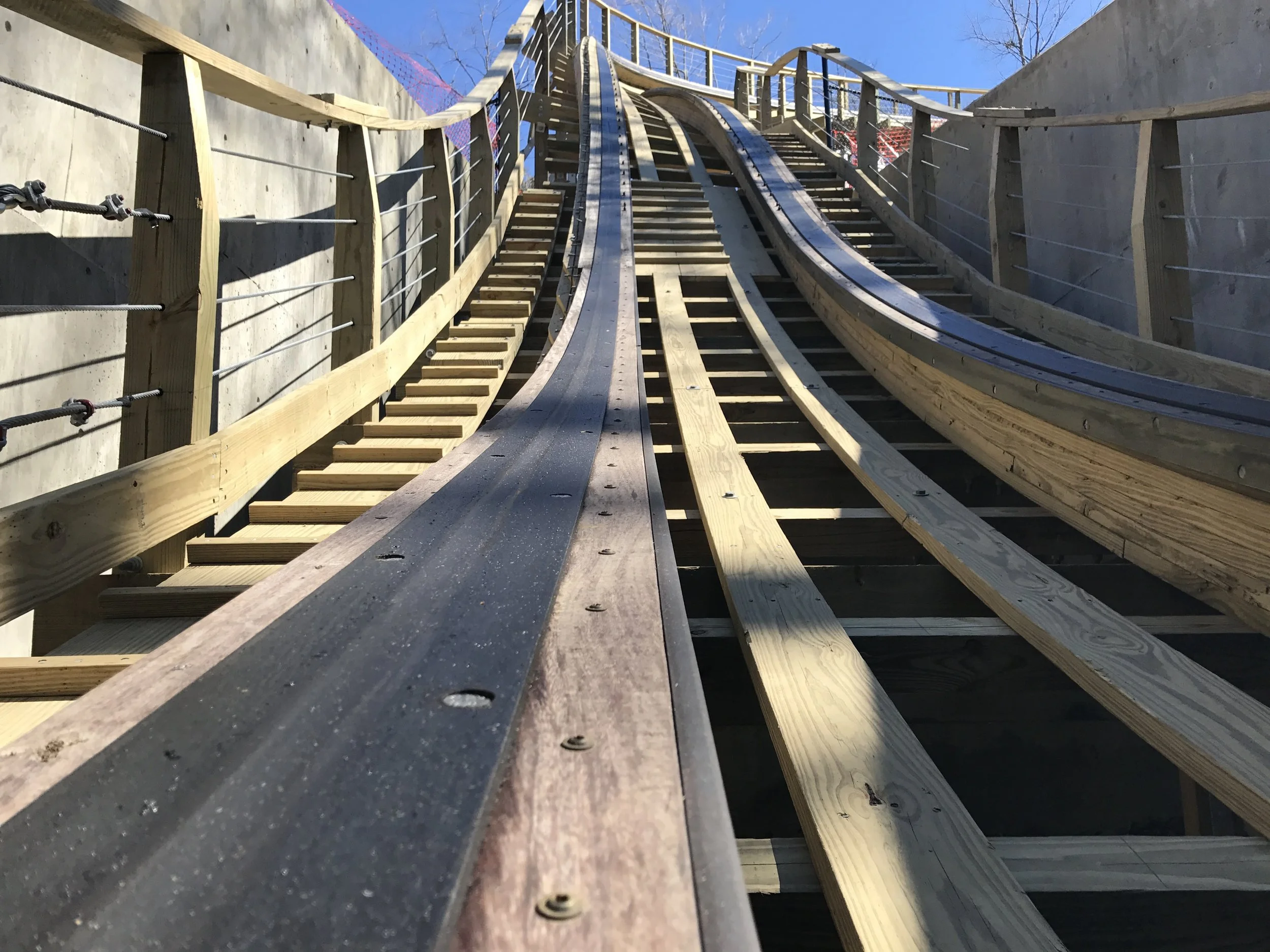
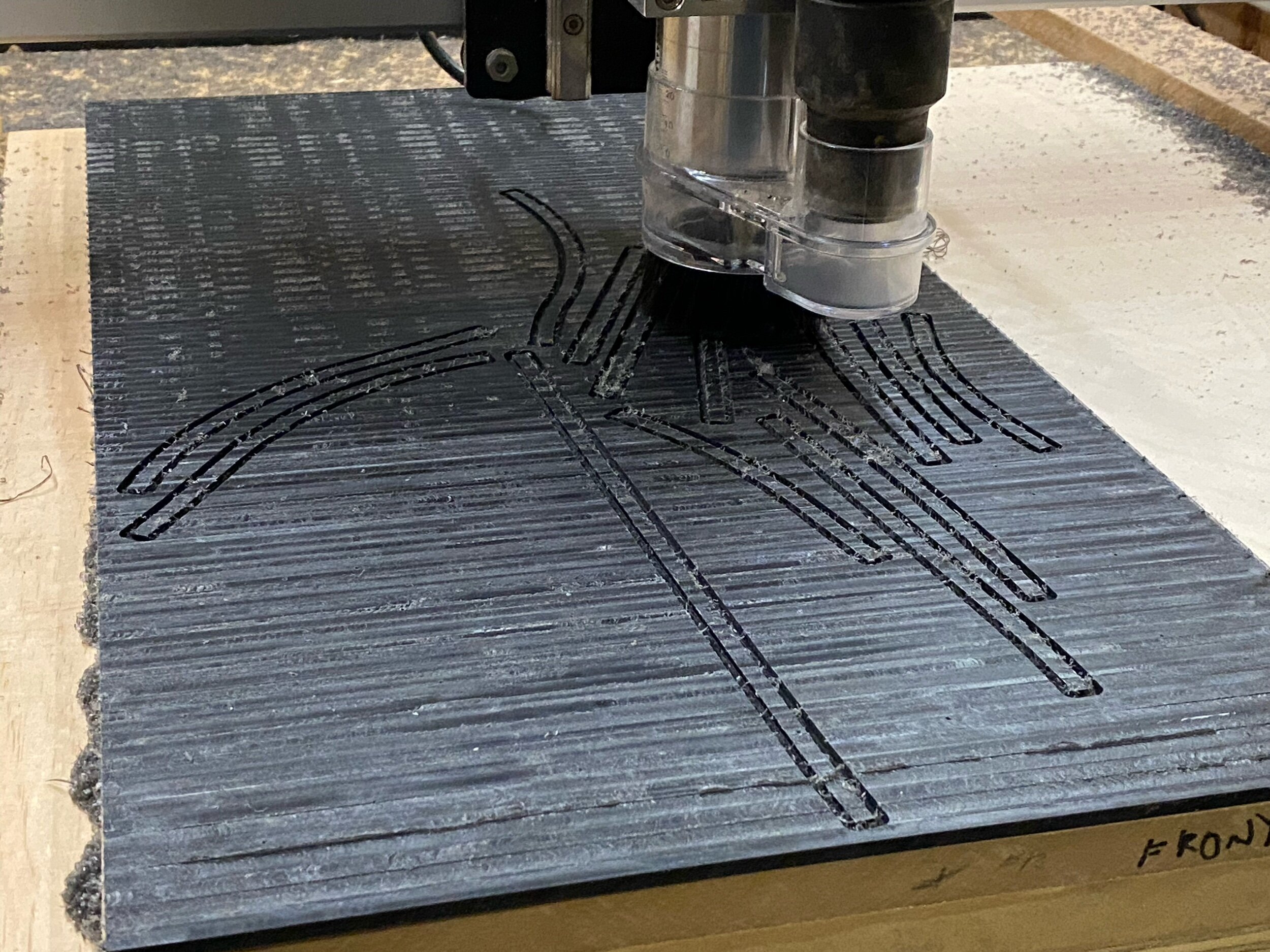
Being that I have created, and successfully tested, math programs to flatten my designed 3D geometry for printing, this seems like a good approach to the traditional methods of building a wood coaster. The track laminates will still be cut and broken down like the modular method, but once each section is created the math programming takes over and flattens each layer. The 3D printer is phenomenal with what is called “2.5D” fabrication generating layer by layer. Although 3D curved models are not actually smooth, flat patterns are consistent throughout. Taking these ideas forward, I can generate the base layer from each support printing in 3D to match the ride’s profiling, then every layer above will be printed flat and bent to form the track. Similar to a real wooden coaster, these plys will have smooth faces on all sides and will match the design precisely. For the guide rails aspect, printing flat patterns ensures the layer lines run along the ride path and minimize the inherent friction. The bottom layer is simply a support feature and doesn’t interact with the cars during ride operation.