
From Centerline To Track
/After completing the last video depicting the fabrication and assembly of the next sections of the ride, it dawned on me that I am about to complete the full structure. With that being said, I need to complete the detailing of the ride’s track. Since wooden coasters are traditionally built in the field and cut by skillful carpenters, most detailing revolves around good practices and standards. Meaning, this little wooden coaster will not be built in the classic sense.
So how is this little ride going to be built, track-wise? This ride will be constructed similar to a steel roller coaster utilizing prefabricated track sections. Intamin (a large ride company) and Rocky Mountain Construction (another company) incorporate prefabricated sections in their building of wooden roller coasters. The latter sometimes using only steel track on a wooden structure. In order to detail and prepare the track sections for machining requires some finesse. What I mean is that I will have to produce extra points along the track path from the ride centerline.

Interested in more detailed coaster designing? Checkout the Patreon! https://www.patreon.com/therollercoasterproject
The photo shows every point along the track center of the ride at each support (bent). One problem with using this few of points: error of spline creation. Fusion 360 has multiple scripts created for ease of producing drawing features. Perhaps one of the best scripts is the importing of CSV data from Excel (or your favorite brand of tabulation software…I don’t care too much, so HA!) and connecting the points with a cubic spline. A cubic spline? Yes, a cubic spline that is created to pass through every imported point. Cubic splines are extremely accurate, to a fault…

In areas where the centerline of the ride travels from a “straight” section to one with curvature…fancy for curved section…too few data points cause the spline to bow in and out of the path. This is extremely problematic when creating the track pieces. If I keep the spline as is currently, then the track will have chaotic bowing and, let’s face it, the ride will look like trash.
So what do we do? We calculate extra data points along the track and centerline. We already have the equations for the ride, so producing more points along the path will be somewhat easy. In the future, this will have to be streamlined with an external program/script to expedite modeling.

Using a sample section of the ride to produce a CSV file, we have the columns from right to left representing X, Y, and Z, respectively. There is an issue with importing into Fusion 360, however. For the life of me, I could not figure out why my data points were spaced out by a factor of ten (10)! Want to know why? For some stupid reason the default import in Fusion 360 is in centimeters (cm) instead of something user defined. This kind of sucks, especially if you don’t realize it. So, after much cursing and throwing of furniture I figured this out and reduced all the values by ten (10) to ensure dimensional accuracy.

Factoring the design values by 1/10 resulted in proper data points. Now, I can insert extra points and produce accurate and smooth track sections. For reference, I chose to add ten times the data points per section. So far, this has not resulted in any issues with the ride pieces.

From the data points, a sweep operation in Fusion 360 along the path with the track “profile shape” is performed. The above track section is between Bents 116 and 118.
I’ll be working on finishing the remainder of the coaster structure this coming week and will be adding the track sections, afterward. This is getting exciting as the ride is coming together and I look forward to sharing more with you guys in the future!
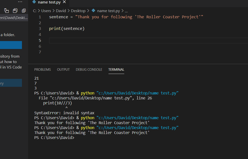
Learning Python to expedite ride design.