
The Next Sections
/This week saw the fabrication of the next few sections of the mini wooden coaster. The next sections to be stood will comprise Turns 1 and 3, the station sections and brakes, and the first drop that leads to the second turn.

The end of these segments is the beginning of the new.
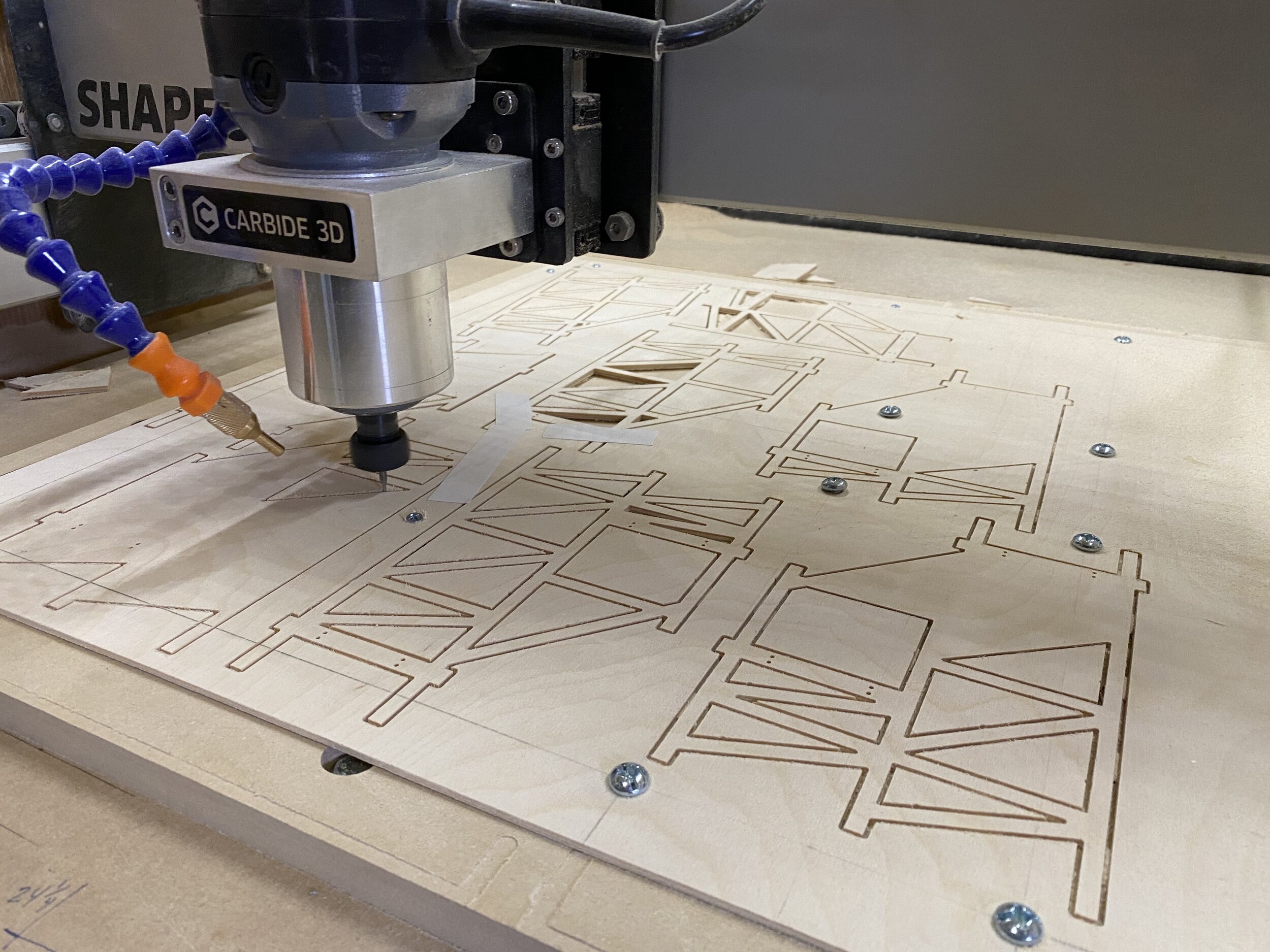
Changing my machining approach from last time, I decided to implement a more appropriate work holding solution: tabs. Unfortunately, using tabs or any excess material holding option results in lengthy finishing operations. These finishing operations are typically performed manually; however, sometimes you can program an additional machining operation to clean excess material. For these small supports, tabs will have to do.
A few issues…per usual.
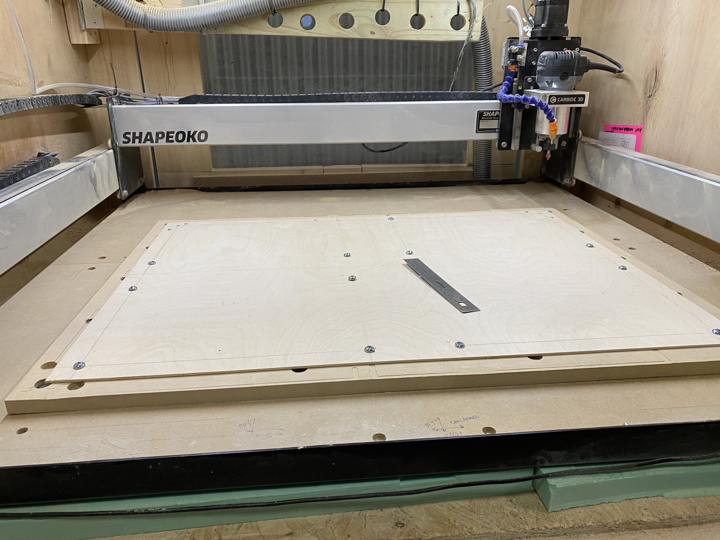
For the previous section, I was physically attaching the plywood sheet to the MDF waste board with small wood style screws. Since the waste board becomes damaged every time you drill or screw into the surface, I thought of ways to preserve the MDF a bit longer. My plan was to drill through-holes in locations that aligned with the threaded inserts in the MDF waste board. I had a few issues with getting exact alignment. (It just never stops)
David seems a little down…
Don’t worry, it’s said you learn more from failures than from successes. I think the one thing you don’t learn is how to not fail, nevertheless it was a minor headache aligning the bolts. Eventually, the sheet was secured. Also note, this time I did not place any double-sided tape to maintain flatness.
Calm before the s*** storm (kidding)
To ensure I wouldn’t place a screw in the location of a bent (support), or rather a support in the location of a screw I modeled the layout in Autodesk Fusion 360. I am taking advantage of Fusion 360’s powerful machining features which surpasses my needs, but the powerful features allow me to organize the ride supports evenly.

It “should” work.
In theory, the supports are going to be spaced appropriately so as to not cause a collision with the router and holding screws. One thing I completely forgot was to check the clearance distance the router retracts in order to move rapidly. Basically, if the router doesn’t retract high enough the small cutting tool will collide with the screw head (stainless steel) and break. Fortunately, I ordered multiple 1/16th inch downcut wood end mills from 2Linc out of Massachusetts. Despite the surplus and cost of the end mills (cutting tools), I would like to avoid hitting anything.

Nearly filled my pants…yes.
As you can see, I came within a few millimeters of the screw head and decided to dance with the devil a bit. But, to my surprise, I did not hit any of the screws. For the final, production, fabrication I will increase the passing distance to ensure I don’t accidentally shatter my dreams, I mean tool.
But there was another issue…
From the second picture in this post, you probably noticed something funny about a few of the supports. I think you did. I mean, I can’t really tell what you’re thinking, but I like to try. We all do it, stop judging me. Thank you.
Moving on, the issue with the supports in some areas was caused by the plywood being warped. Damn wood. With portions of the plywood being warped and not at a consistent height, the cutting tool would dive deeper than anticipated and cut my holding tabs. The result of cutting some of the internal tabs prematurely was sections of wood becoming lodged under the plywood sheet, flinging wood across the CNC, and much anxiety. Fortunately, this didn’t cause any final issues with the parts overall. However, I did have to pause the operation a few times to clear any wedged wood…lodged wood…wood stuck under the plywood sheet.
Don’t worry, I’m not crazy, just trying to liven this up a bit.

Got more tape on the face than Nelly.
Aside from the plywood looking like it lost a fight and it being a tad ghetto fabulous, the final parts turned out spot on. There were only a few areas where warping was excessive causing these “occurrences.”
Going forward, I will be attempting to flatten the plywood out a bit. I have read a few methods and have seen some successes. Since wood is an organic material, a straight piece can be nearly impossible to find. Even plywood, which is manufactured to be consistent can have imperfections.
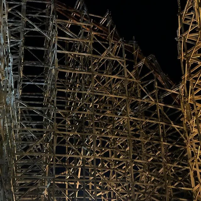
Does this happen in the real world with wooden roller coasters?
Yes, actually, the bents when stood are never straight. This is referred to as being out of “plumb.” To combat and correct the issue of warping and not being spaced appropriately, wooden roller coasters implement what are “ribbons.” These ribbons help to stitch the structure together and maintain an perfectly plumb ride structure.

Wickerman at Alton Towers with some temporary ribbons and final ribbons.
Starting with temporary bracing held with nails into the post will allow workers to straighten the ride supports as necessary. A worker on the ground using a surveying tool will work in tandem with the structure crew to ultimately verify that the ride is perpendicular to the ground.
Back to the mini coasters…
The mini coaster will incorporate some form of ribbon which will be determined later, but the track rails will help to maintain spacing at the top of each support. To not rely too much on the other components, it will be important for me to flatten the plywood as much as possible going forward. I will provide updates as they become available.

Stacks on stacks
Once all of the bents were cut, I used the oscillating tool and a chisel to separate the parts from the remaining plywood sheet. Removing the parts is time consuming, so if anyone out there has a better idea or a more efficient method please tell me. FOR THE LOVE OF GOD PLEASE TELL ME. Sorry, a bit dramatic, but it did take nearly as long to separate the parts as it did machining them.
…wait, I am like a machine? Hmm.
Moving on.
For a real wooden roller coaster, the bents are assembled on top of each other so I thought it nice to do the same…sort of. The production product will have engraved bent numbers making it a bit easier to determine which bent goes where, but for this prototype I needed to place the bents in order so they are installed in the correct location.
They also look really cool when you see them from the front.

Soon to be installed.
Coming up, I will have another video covering the new sections and some extra features about the ride’s construction. Be sure to follow along on YouTube “The Roller Coaster Project” to see the ride in action and for some cinematic excellence. Talk to you guys soon!