
A Miniature Coaster in the Works
/As the year comes to a close, a few things have happened to us all. In my life, I was able to resume building wacky little roller coasters and have ceased to work for an amusement ride company. I know, heavy right out the gate. Although I’m far from the only one to have had such unfortunate events affect their life, I think it’s good to look on the positive side and add up what remains: design experience, health (hopefully everyone else too), charming humor, and handsome good looks… Perhaps I’m a bit delusional.
Since I was able to resume building miniature coasters, I shifted my focus from a ride the scale of 1:22 the actual size to a more common gauge: O-Scale (1:48).

The Test Section - Proof of Concept
Since running the Kickstarter, the idea of building a smaller version of the roller coaster had been in my mind. It was actually one of the rewards (I still plan to make good on my obligations). Until now, how to fabricate such a small and exact little coaster was proving to be a bit of a pain. With my milling experience limited to the Taig CNC, fabricating wooden supports accurately and repeatedly seemed to be out of reach. The key would be a CNC Router or Laser cutter if I were going to produce accurate bents (supports).
Enter Carbide3D…
At about the same time I was wrapping up my Kickstarter, a small company from California named Carbide3D was beginning theirs with an all-in-one turn key CNC mill for the desktop. Having just purchased the Taig, I was not in the market for any other CNC equipment. However, Carbide3D was successful in launching their Nomad CNC and eventually produced a router called the Shapeoko. The Shapeoko would utilize a hand rotary tool at first, but through various iterations the spindle would become a 1.25 Hp palm router. The frame would be strengthened and accuracy improved over time.
The Shapeoko XXL
Prior to the world “locking-down,” I had been looking for ways to get back into building the mini coasters. I sought out a local Makerspace and even went to an orientation to join. As I was looking to join, things began to change. Businesses were closing up, people were working from home, and makerspaces halting operations. Since my determination to build some mini rides never faltered, I began looking around for a small CNC to help me achieve my goals.
I had been following Carbide3D for some time, and I knew of their Shapeoko 3. From the reviews, its price point and robust frame seemed like a good fit.

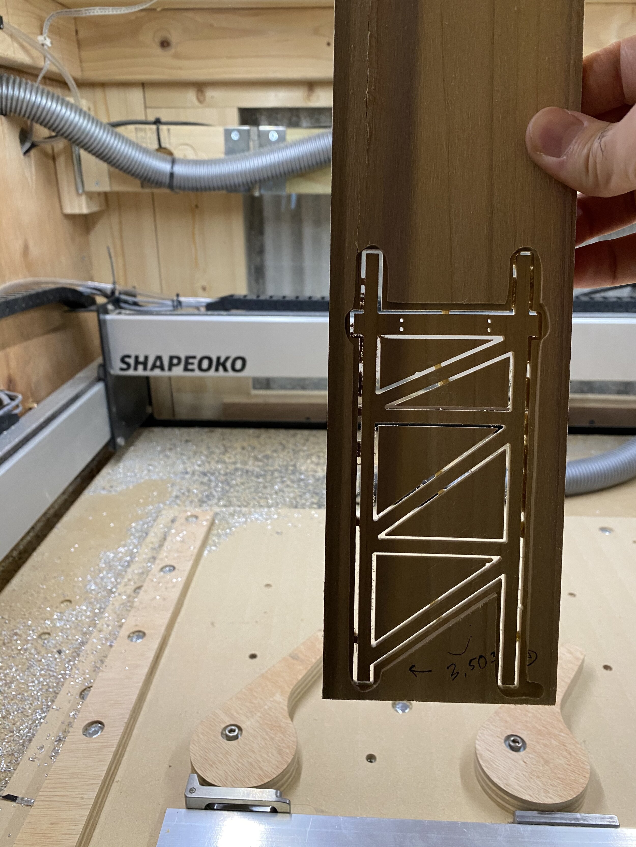
Shapeoko XXL Cutting its First Bent!
I decided on their larger size Shapeoko XXL due to its large cutting area. With a cutting area of approximately one (1) square meter, I could layout an entire baseboard foundation for the mini coasters and have the CNC mill the exact locations for the supports. Since I had little experience milling wood, I knew there would be a learning curve, too.
Fortunately, using the CNC Router along with Carbide3D’s intuitive software made learning the ins-and-outs of the Shapeoko truly enjoyable.
The Test Section
Through my practice cuts and design iterations, I knew fabricating a test of final assembly was crucial. The test section would have to incorporate each aspect of the structure and similar hardware that would be used on the final design. With this test section, it would be a good opportunity to develop miniature rollingstock (the cars).

Fusion 360 to model it all.
The ride structure would be comprised of the supports, track brackets, and track rails. For a real roller coaster, the track is typically laminated and the first layer is nailed into the ledger (horizontal beam between supports) with 3-5 heavy nails. Now, the original nails come out or break off as the ride runs the first few times, but the weight of the track stack holds everything in place. Yes, the track is not connected to the ride. Most bridges are constructed in a similar way and the weight of the beams holds the bridge intact.
The materials I used for the test section and will make up the final version are Baltic Birch plywood for the structure (thanks to Matt from PrintMyRide…follow him on Instagram @PrintMyRide), Acetal Delrin for the track brackets and some type of flexible plastic for the rails. For the test section, the track rails were milled out of Delrin plastic, but I plan to use LDPE due to its flexible properties.

These screws are 1/16 of an inch in diameter and the bracket is less than a quarter of an inch in thickness.
Once the track was connected to the brackets with “self-tapping” sheet metal screws, the overall ride became surprisingly rigid. Each track section was created based on the designed centerline, and the placement of the ledger is then based on the location of the track. The hardest portion of the test section proved to be the track brackets. I went through three (3) versions of the bracket prior to settling on the above version, and the final design looks and performs tremendously.
So let’s make more!
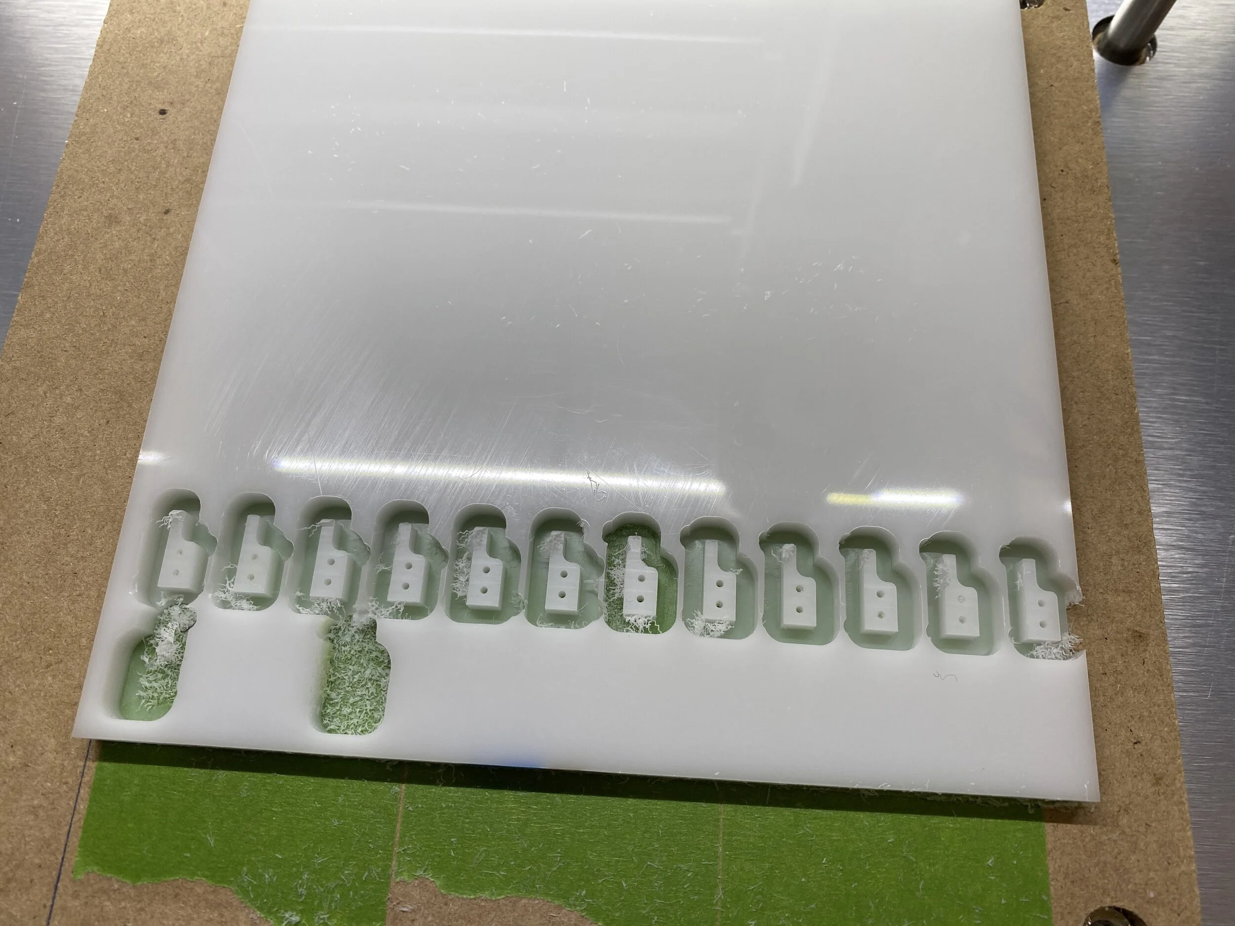
Had some white Delrin available, but final color will be black. The drilled holes are 1/16” in diameter.
Using the Shapeoko, I milled out the remaining parts necessary to construct the test section. Setting up in Fusion 360 (CAD program from Autodesk), and utilizing their new features for flat patterns allowed rapid production of the full design. Once the code was prepared from the design, I affixed the plywood to the CNC and began cutting the bents.
Successful Bent!
With all supports milled, brackets finished, and baseboard routed, I began to assemble the test section similar to an Erector Set. The small hardware was a tad difficult, but with proper tools from iFixit, such as miniature hex screw drivers, I was able to tighten the hardware appropriately.

Being that this is only a test of the final assembly, a few things need to be solved: connection between track segments, sanding of supports, and handrails and walkboards. However, this little test was a success and allowed me to begin development of the cars.
More to come soon, along with videos to go through the progress!