New Design Programs
/It has been a while since my last update, but I assure you that I have been up to - some good. My latest dilemma in the making and designing of a mini-working roller coaster is fundamentally what makes a real, full sized, coaster complex: track location. More specifically, where will the track rails be at any given increment as the centerline progresses around the circuit. Sounds like a lot, eh? It is and it isn’t.
Moving on…
My goal for this first mini coaster is to not incorporate any banking to simplify the designing and fabrication. Much to my chagrin (Yes, I did just use that statement from middle school vocabulary), this wasn’t any simpler than banking the s*** out of the coaster layout. At least, designing isn’t any more difficult. The real problem comes from the fabrication of the ride. In order to streamline production, I opted to perform as little setup and multi-op machining as possible. The drawback to this strategy is that I will have to add some “finishing” tactics post machining.
Initial Designs
From the ride’s inception, the idea was to mill the track sections in one-fell-swoop (thank you Nate Bargatze for his joke about that damn expression…checkout his stand-up comedy special for reference). The track lip is roughly 1/16” square, and being that it is so small there exists a high likelihood of error if the CNC is not square. From the “L” shape, mounted track brackets will have a through-hole for placement of a small plastic threading screw. This screw would be fed into an undersized hole resulting in a tight consistent fit. Sounds good, right?
Now the issue…
As the track moves around the ride circuit, complex 3D geometry is produced despite simple geometry being used on my part. For a normal wood coaster, the track is cut in the field by experienced artisans and carpenters who take pride in achieving butter smooth results. This really depends on the company, too. The issue with a prefabricated coaster is now I have to provide a machining path for my CNC to follow. This is similar to a steel roller coaster, and the complexities begin to increase heavily.
Why did you mention new computer programs?
“When am I ever gonna need to know this stuff?” NOW.
The programs I am having to utilize as of late are Matlab and Python for calculations and automation, respectively. With the math programs, I can accurately define where each track rail will rest in 3D space. Currently, I have yet to automate anything more than a headache, but I’ll figure something out soon.
Now for fancy-looking stuff! (3D Modeling, that is.)
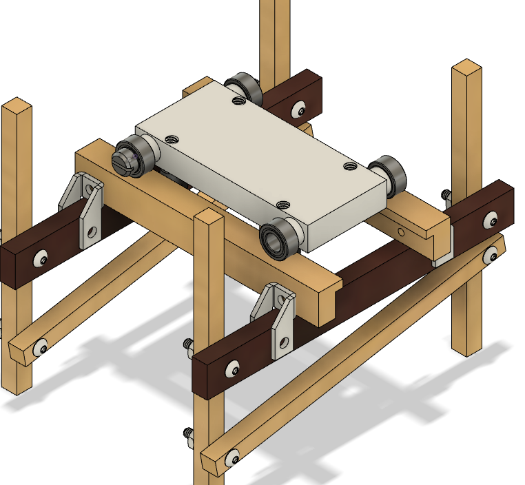
A side-by-side of the new and the old.
If you’ve followed along for a while, you know I have had my issues with Autodesk Fusion 360. Though this software has come a long way since it was first rolled out and “yours truly” tested it out, I have had issues with the cloud storage structure. Basically, a few of my files would become “unavailable.” Yeah, that’s some buhhhshit! (Not a typo)
So what is my solution? I have none, but there may be one. Huh? I have a different program to test out prior to making the monumental shift from Fusion 360. Ideally, I would use Autodesk’s Inventor since it’s the Rolls Royce software and can handle thousands of assembly parts in one file with ease. I may be a tad biased…
What is the newer program, you ask? Well, it’s Alibre Design. Alibre is a 3D modeling program that offers a “one-time” fee and stand-alone service. Yes, “ONE-TIME” fee. With the world moving toward a “rent all your shit for life” model (paradigm), it’s nice to find some companies that stick to a more traditional transaction. Again, I am not fully invested as of yet, but I will be playing around with the features going forward. As of now, the ease working with large assemblies is far superior to that of Fusion 360. However, the drawback for the Design package is that it does not offer a CAM (computer aided manufacturing) feature as Fusion 360 natively incorporates. There is an additional package to add to Alibre Design that allows up to 3-axis machining, and for my “basic bitch” skills that will be more than enough. Time will tell, but this is where I am, currently.
Street Car!


